
User guide

Max Machinery, Inc. 210 Series User Manual © Copyright 2013 Rev. 002Q4 10
Installation
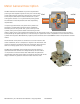
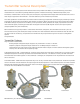
For optimum performance, install the ow meter in one of the congurations shown below. The following items and
conditions should be considered:
Line and Bypass Valves: These valves allow lter cleaning or ow meter removal without completely shutting the system
down and draining the lines. They also allow system start up under conditions which could damage the meter; such as:
air in the lines, high temperature materials, or initial line surges.
Filtration: Clearances between the ow meter piston and cylinder wall are typically 0.0002” to 0.0004”. Any dirt
present in the system can jam or damage the unit. A 10 micron lter (such as a Max 381 Series stainless steel unit) is
generally recommended, although materials with very high viscosities may require a coarser lter. For bidirectional ow
applications, use a lter on each side of the ow meter. Materials with brous or non abrasive particulate matter may
have to be run without lters. Follow the recommendation of your Max Sales Engineer or consult our Technical Service
Department.
Inlet and Outlet Ports: Use the “IN” port as the inlet for the most predominant ow direction. Install the ow meter on
the discharge side of the pump whenever possible. Excessive vibration at the meter should be avoided.
High Temperatures: Use the “Vertical Installation” drawing. This minimizes heat transfer by convection from the ow
meter to the transmitter. The transmitter is the most heat sensitive element in the system and the transmitter manual
should be consulted for specic limits. An optional uid heater block can be used on the ow meter to keep it at
operating temperature during standby conditions. For substances that are solid at room temperature, the block may be
required to keep the material molten and owing through the meter.
Clean Plumbing: Before installing the ow meter, clean the inside of the pipe line with compressed air or steam
(especially when using new pipe). Don’t use water, steam, or compressed air on the meter itself!
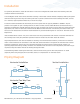
Piping Diagram
FILTER
VALVE 2VALVE 1
FLOW METER
VALVE 3
FLOW
BYPASS
FILTER FILTER
VALVE 2VALVE 1
FLOW METER
VALVE 3
FLOW
BYPASS
FILTER
VALVE 1
VALVE 2
FLOW METER
VALVE 3
FLOW
BYPASS
Horizontal Installation
Horizontal Two-Way Flow
Vertical Installation