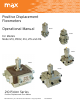
Positive Displacement Flowmeters Operational Manual Model Model For Models Model 213, P002, 214, 215 and 216 Model Model Model 210 Piston Series Positive Displacement Flow Meters Max Machinery, Inc. 210 Series User Manual © Copyright 2013 Rev.
Table of Contents Before You Install................................................................................... page 3 Meter General Description................................................................... page 4 Transmitter General Description........................................................ page 5 Meter Specifications............................................................................. page 6 Transmitter Specifications Analog....................................................
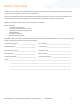
Before You Install Thank you for choosing to install a Max Machinery precision flow meter. To ensure the best experience please take a moment to read through this manual prior to installation. When you purchased this meter a flow engineer helped determine many of the factors that will be reviewed on the following pages. You may find it useful to fill out the form below and keep it in your files for reference.
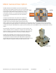
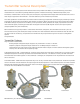
Meter General Description The Max 210 Series Flow Meters are positive displacement piston type units capable of great accuracy over a wide range of flow rates and fluid viscosities. The four basic sizes of this series (213, 214, 215, 216) will measure flows from 1 cc/min to 25 gal/min. Various “O” ring and internal plating options are available to meet temperature and fluid compatibility requirements.
Transmitter General Description Max transmitters are designed to work with the entire family of Max Flow Meters to provide extremely precise flow measurement in a cost effective package. Different options of industrial housings or IP66 rated explosion proof enclosures, combined with a choice of one-part and two-part, high temperature designs with remote electronics cover a wide range of application environments – from the laboratory to harsh industrial processes.
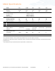
Meter Specifications Model 213 P002 214 215 216 1 Maximum flow rate Gal/min: 0.48 0.53 2.64 9.25 26.4 Liters/min: 1.8 2.0 10 35 100 Maximum pressure (psi) 2xx-3xx, 2xx-4xx: 1,000 psi (70 bar) 2xx-6xx: 3,000 psi (210 bar) P002, 214-5xx 7,250 psi (500 bar) Pressure drop (PSIG) Operating maximum: 15 15 28 30 30 Absolute maximum: 20 20 30 42 42 100% Flow (3cps): 3.25 3.25 3.
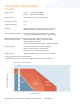
Transmitter Specifications Analog Supply Voltage 12 Vdc 24 Vdc (Models 29X-XXX-100) (Models 29X-XXX-000) Supply Current 90 mA max@ 12 Vdc, 45 mA max@ 24 Vdc Short Circuit Current 21 mA 1 Output Update Rate 1 ms Adjustable without recalibration to any range of ± 10 Vdc Model 29X-3XX-XXX or ± 20 mA Model 29X-2XX-XXX Resolution Ambient Temperature Range Transmitter (Storage)–40ºC to 85ºC (–40ºF to 185ºF) Transmitter (Operation)–40ºC to 80ºC (–40ºF to 175ºF) 2 Maximum Temperature, Process
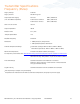
Transmitter Specifications Frequency (Pulse) Supply Voltage Supply Current 5-26 Vdc 25-30 mA typical Output (5.0 Volt Supply) (TTL and CMOS compatible) No Load 2.5K Load to Common 2.5K Load to +5 Volts 0.00 / 4.80 Volts 0.00 / 4.60 Volts 0.25 / 4.80 Volts Short Circuit Current 45 mA Output Impedance 100 Ω Rise/Fall Time 1 Output Update Rate 0.
Do’s & Don’ts DO: Install bypass plumbing around the flow meter. This is useful during start up for removing dirt and air from the plumbing or when measuring fluid that may freeze inside the line and need to be remelted before it can pass through the meter. It also allows removing the flow meter for service without disabling the system. DO: Be very careful to keep parts clean during installation or teardown.
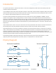
Installation For optimum performance, install the flow meter in one of the configurations shown below. The following items and conditions should be considered: Line and Bypass Valves: These valves allow filter cleaning or flow meter removal without completely shutting the system down and draining the lines. They also allow system start up under conditions which could damage the meter; such as: air in the lines, high temperature materials, or initial line surges.
Operation Determine that the following parameters of your flow metering system are within the specifications for the specific 210 Series Meter being used: Maximum System Pressure (Specifications) Differential Pressure across meter (Pressure Drop Curves) Maximum Flow Rate (Pressure Drop Curves) Metered Fluid Temperature (Sales specification, transmitter specifications page 7) If the metered fluid is greater than 80°F (28°C) over ambient, see the “High Temperature Start Up” section below.
Electrical Installation - Wiring Removal note: The transmitter does not need to be removed from the flow meter for any field servicing or adjustments. Normally, the flow meter and transmitter are shipped back to the factory for calibration or service as a unit. If the transmitter needs to be removed from the flow meter for installation, be sure to retighten the transmitter snugly in order to ensure proper sensor alignment. Mechanical Installation 1.
Electrical Installation - Wiring Wiring FREQUENCY The electrical connector versions are pre-wired inside the transmitter and ready to accept a mating cable (available from the factory).
Troubleshooting Trouble Corrective Action No Flow through meter or high pressure drop across meter Solidified material blocking rotation Heat meter to melt material Debris blocking rotation Remove plumbing base, inspect crankshaft and piston rods for damage.
213 Piston Flow Meter 2.26” 2.61 SQ” (57mm) (66mm) 1.5 SQ” 1.93” (38mm) (49mm) 1/2” NPT 1.125” in (29mm) out 5.98” (152mm) 5.47” BOTTOM VIEW BOTTOM VIEW (139mm) 2.26” (57mm) 2.26” mounting holes 10-32NF (6) places MODEL 213 WITH INDUSTRIAL HOUSING (57mm) 0.625” (16mm) * SAE base adds 0.375" (10mm) to height and 0.5" to face to face dimensions 0.
P002 Piston Flow Meter 2.26” (57mm) 1.96” 2.26” (50mm) (57mm) 5.98 5.51 (152mm) (140mm) 3.62 3.62 (92mm) (92mm) MODEL P002 WITH INDUSTRIAL HOUSING TRANSMITTER MODEL P002 WITH EX-PROOF HOUSING TRANSMITTER Inlet port locations 2.26” (57mm) 2.26” (57mm) BOTTOM VIEW 0.65” mounting holes 10-32NF (4) Places (17mm) not to scale EX-PROOF HOUSING TOP VIEW TYPICAL PRESSURE DROP (Delta P versus Flow rate for various viscosities) 35 Pressure Drop (psi) 30 —2 bar 25 20 15 —1.
214 Piston Flow Meter 2.26” (57mm) 1.93” (49mm) 1/2” FNPT 6.61” 6.3” (168mm) (160mm) 2.57” 2.57” mounting holes 1/4-20NC (6) places (65mm) (65mm) 1.125” MODEL 214 WITH INDUSTRIAL HOUSING TRANSMITTER (29mm) MODEL 214 WITH EX-PROOF HOUSING TRANSMITTER 2.26” 4.875 SQ” (57mm) (124mm) 2.26” (57mm) 2.125” in (54mm) 3.00 SQ” out 0.
215 Piston Flow Meter 2.26” 1.93” (57mm) (49mm) 1/2” FNPT 7.99” 7.48” (203mm) (190mm) 3.93” 3.93” (100mm) (100mm) mounting holes 5/16-18NC (6) places MODEL 215 WITH INDUSTRIAL 2.0” (51mm) MODEL 215 WITH EX-PROOF HOUSING TRANSMITTER HOUSING TRANSMITTER 4.95 SQ” 2.26” (125mm) (57mm) 2.26” 7.88 SQ” (200mm) in out (57mm) 2.125” (54mm) 0.
216 Piston Flow Meter 2.26” (57mm) 1.93” (49mm) 1/2” FNPT 9.45” 8.94” (240mm) (227mm) 4.825” 5.39” (123mm) (137mm) mounting holes 3/8”-16NC MODEL 216 WITH INDUSTRIAL ^t (6) places 3.0” (76mm) HOUSING TRANSMITTER MODEL 216 WITH EX-PROOF HOUSING TRANSMITTER 7.0 SQ” (178mm) 2.26” (57mm) 3.00” in (76mm) 2.26” 9.5 SQ” out (57mm) (241mm) 0.
Contact for Repairs & Calibration Services The Max 210 Meter Series is not designed for user repair and all such work should be done at the factory or under the direct supervision of the Max Technical Service Department. Unauthorized repair work may damage the meter and will void the product warranty. Please make note of model and serial numbers on the flow meter before calling the factory. A return goods authorization number will be issued if the flow meter has to be sent back for repair.