
Manual

120-200-350 © 1993 (Rev 5/97) Max Machinery, Inc. Page 23
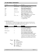
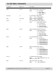
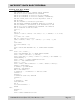
Command Response Description
QTC ATCaaaaaaaaaa QUERY TOTALIZER COUNT
where aaaaaaaaaa = Totalizer Count
QRH ARHaaaaaa QUERY RATE HI SETPOINT
where aaaaaa = Rate Hi Setpoint
QRL ARLaaaaaa QUERY RATE LO SETPOINT
where aaaaaa = Rate Lo Setpoint
QTS ATSaaaaaaaaaa QUERY TOTALIZER SETPOINT
where aaaaaaaaaa = Totalizer Setpoint
QMD Aa... QUERY MENU DATA
where a... = Data Specified in Current Menu
QAP Aab c... ab c... ... QUERY ALL PROGRAM DATA
where a = Program Menu Row
b = Program Menu Column
c = Applicable Data
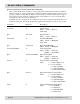
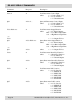
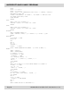
Load Run Data Commands
This classification of commands allows the computer to write setpoints to the indicator and
specify the indicators response to the QMD command. These commands are valid only in the
run mode. The following Load Run Data Commands are supported:
Command Response Description
LRHaaaaaa A LOAD RATE HI SETPOINT
where aaaaaa = Rate Hi Setpoint
LRLaaaaaa A LOAD RATE LO SETPOINT
where aaaaaa = Rate Lo Setpoint
LTSaaaaaaaaaa A LOAD TOTALIZER SETPOINT
where aaaaaaaaaa = Totalizer Setpoint
LCMab A LOAD COMMUNICATION MENU
where ab determine the information that will be
sent by the control when it is issued a QMD
command. The following table illustrates the bit
assignments for the available data. Setting the
appropriate bits will cause that data to be sent.
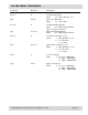
Digit “a” Bit 0 Status
(0-F) Bit 1 Flow Rate
Bit 2 Rate Low Setpoint
Bit 3 Rate High Setpoint
Digit “b” Bit 0 Totalizer Count
(0-F) Bit 1 Totalizer Setpoint
Bit 2 K-factor
Bit 3 Rate Multiplier
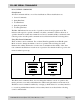
RS-485 SERIAL COMMANDS