INSTRUCTION MANUAL 120 FLOW RATE & TOTAL INDICATOR Table of Contents General Description . . . . . . . . . . . . . . . . . . . . . . . . . . . Pg 2-3 Specifications . . . . . . . . . . . . . . . . . . . . . . . . . . . . . . . Pg 3-4 Display & Setpoint Functions . . . . . . . . . . . . . . . . . . . Pg 5 AC Power Wiring . . . . . . . . . . . . . . . . . . . . . . . . . . . . Pg 6 Case Size & Panel Mounting . . . . . . . . . . . . . . . . . . . . Pg 6 Rear Panel Connections . . . . . . . . . . . . . . . . .
GENERAL DESCRIPTION General Description The Max 120 Flow Rate & Total Indicator performs two basic functions. It totalizes all flow and calculates flow rate. Totalizer The totalizer has a ten digit display, and is equipped with a scaler to accept flow meter K-factor values from 0.0001 to 99999. The Reset key can be programmed to reset the totalizer count. The totalizer inhibit input can be used to stop the count. The totalizer is unidirectional; it counts up only.
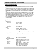
GENERAL DESCRIPTION / SPECIFICATIONS General Description (cont.) The rate meter displays zero rate when the time interval between input pulses exceeds the programmed rate zero time. The timer can be set from 1 to 15 seconds. The rate units of measure (up to three characters) can be programmed into the unit and will be shown along with the rate value and rate setpoints on the display.
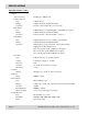
SPECIFICATIONS Specifications (cont.) • Outputs Accessory Power: Totalizer Setpoint Type: Rating: Operation: Rate Alarms: Type: Rating: Operation: Scaled Pulse: Type: Rating: Operation: • • • • Flow Rate: Type: Voltage: Response: Accuracy: Resolution: Totalizer Display K-Factor Range: Rate Indicator Type: Display: Accuracy: Rate Multiplier: Rate Smoothing Communication Type: Baud Rate: Parity: Page 4 24VDC ±5%, 100 mA max 1 NPN transistor 150 mA maximum, 30 VDC maximum Latched or timed from 0.01 to 99.
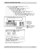
DISPLAY & SETPOINT FUNCTIONS 120-200-350 © 1993 (Rev 5/97) Max Machinery, Inc.
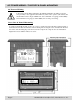
AC POWER WIRING / CASE SIZE & PANEL MOUNTING AC Power Wiring A disconnect switch shall be included in the building installation. It shall be located in close proximity to the equipment and within easy reach of the operator. (All switches and circuit breakers must comply with IEC 947. Use a minimum of 18 gauge (1mm2, 600V) and a maximum of 14 gauge (1.6mm2, 600V) wire for AC power wiring. Case Size & Panel Mounting To panel mount the Model 120, a hole 5.43" x 2.67" is required.
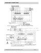
REAR PANEL CONNECTIONS Note: ---> Red is brown on 294 cables Note: ---> Green is blue on 294 cables 120-200-350 © 1993 (Rev 5/97) Max Machinery, Inc.
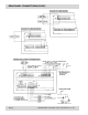
REAR PANEL CONNECTIONS (CONT.) Page 8 120-200-350 © 1993 (Rev 5/97) Max Machinery, Inc.
PROGRAMMING MENUS 120-200-350 © 1993 (Rev 5/97) Max Machinery, Inc.
PROGRAMMING MENUS (C0NT.) Page 10 120-200-350 © 1993 (Rev 5/97) Max Machinery, Inc.
PROGRAMMING Programming PROGRAM CALIBRATE Sub Menu 11 - K-factor Clear key enables entry of new K-factor (up to 5 figures). 0 to 9 and DP keys are used to write the number of flow meter pulses per unit volume to the display. Enter key writes the new K-factor to memory. The reciprocal of K-factor is Kmf low (To read: press up arrow key, then 3 while in the run mode). The K-factor is the number of flow meter pulses per unit of volume (cc, liter, gallon) required to increment the totalizer display one digit.
PROGRAMMING Programming (cont.) • Example 1: Program a system consisting of Model 213 Flow Meter, Model 284 Transmitter. Total display engineering units = xxxxxxxxx.x gal (set D.P. in sub menu 25) Rate display engineering units = xxxx.xx gpm (set D.P. in sub menu 35, units in sub menu 37) K-factor = 111.373 pulses/cc Sub Menu 11 111.373 pulses/cc x 3785 cc/gal = 421,547 pulses/gal K-factor (with decimal place) = 421,547 x 0.
PROGRAMMING Sub Menu 13 - 4-20 mA Output Calibration To calibrate the analog output signal, first turn off all power and then connect the analog output “+” terminal to the 24 VDC out terminal of the control. Connect the analog output “-” terminal to a current meter and connect the other end of the current meter to the 24 VDC ground terminal. Turn power back on and select menu 13.
PROGRAMMING PROGRAM TOTALIZER Sub Menu 21 - Totalizer Remote Control Inputs Any of the five rear terminal control inputs can be programmed to perform a function in the totalizing operation. A control input is selected by pressing front panel keys 1, 2, 3, 4 or 5. Key 1 selects control input 1, key 2 selects control input 2, etc. When a control input terminal has been selected, it is shown on the left hand side of the display and its function is shown on the right hand side of the display.
PROGRAMMING PROGRAM RATE METER Sub Menu 31 - Smoothing Rate is calculated and the rate display is updated every 0.5 seconds. When rate smoothing is selected to be greater than 0.5 seconds, the most recent rate calculation is averaged with the previous rate calculations that were made in the smoothing period. Use the up arrow key to select the amount of smoothing desired. Optimum smoothing is normally obtained by setting the smoothing while the flow rate is at its lowest normal value.
PROGRAMMING PROGRAM RATE METER (cont.) Sub Menu 36 - Rate Meter Zero Time-out The rate meter displays zero rate when the time interval between input pulses exceed the programmed rate zero time. The timer can be set from 1 to 15 seconds. Use the Clear, number and Enter keys to enter a new timer value. Sub Menu 37 - Rate Display Header The rate units of measure (up to three characters) can be programmed into the unit and will be shown along with the rate value and rate setpoints on the display.
RESET KEY & CONTROL INPURT REFERENCE RESET KEY & CONTROL INPUT REFERENCE Reset Key The Reset key is programmable to perform different tasks for the totalizer and rate meter functions of the unit. The Reset key can perform one task under each of the two major control functions shown below. The following table lists the tasks that can be selected. The boxes to the left are to mark your current settings.
RS-485 SERIAL COMMUNICATIONS RS-485 SERIAL COMMUNICATIONS The Max 120 Indicator is equipped with an RS-485 serial communication port for the purpose of allowing a computer to: 1. Issue control commands such as reset. 2. Query run mode data such as count, rate, setpoints, etc. 3. Load setpoints. 4. Query and program all program mode sub menus except numbers 13, 15, 42, 43 & 44.
RS-485 SERIAL COMMUNICATIONS RS-485 SERIAL COMMUNICATIONS (cont.) Description Of Data Format The serial data format consists of a start character (>), a two character unit ID number, a three character command, data for the command (if applicable), a two character checksum and a termination character. The unit ID number and the checksum are in ASCII hexadecimal and have a range of 00 to FF.
RS-232-C TO RS-485 CONVERTER RS-232-C TO RS-485 CONVERTER If you have a computer which has a RS-232-C port and no RS-485 port, it is possible to communicate with a Max 120 Indicator using a RS-232-C to RS-485 converter. If you have tried to interface two pieces of equipment from different manufacturers, you know that the serial communications can be a hassle because there are so many ways to do it while still meeting (or almost meeting) the standard.
RS-485 SERIAL COMMANDS RS-485 SERIAL COMMANDS Classifications All serial commands fall into one of five classifications. These classifications are: 1. Control Commands 2. Query Run Data 3. Load Run Data 4. Query Program Data 5. Load Program Data The Max 120 Indicator has two modes of operation: run mode and program mode. The indicator will respond to specific commands only if the command is valid for the mode of operation the unit is in when the command is received.
RS-485 SERIAL COMMANDS Control Commands All commands in the following tables are preceded by the start character (>) and unit number and succeeded by the two character checksum and carriage return. Command Response Description RSTa A RESET COMMAND where “a” determines functions to be performed.
RS-485 SERIAL COMMANDS Command Response Description QTC ATCaaaaaaaaaa QRH ARHaaaaaa QRL ARLaaaaaa QTS ATSaaaaaaaaaa QMD Aa... QAP Aab c... ab c... ... QUERY TOTALIZER COUNT where aaaaaaaaaa = Totalizer Count QUERY RATE HI SETPOINT where aaaaaa = Rate Hi Setpoint QUERY RATE LO SETPOINT where aaaaaa = Rate Lo Setpoint QUERY TOTALIZER SETPOINT where aaaaaaaaaa = Totalizer Setpoint QUERY MENU DATA where a...
RS-485 SERIAL COMMANDS Query Program Data / Load Program Data Commands Query commands allow the computer to read program data from the indicator and load commands allow the computer to write program data to the indicator. Each command consists of an L(load) or a Q (query) and the two digit submenu number of the program mode sub menu illustrated on page 6. All program mode sub menus are serially accessible except numbers 13, 15, 42, 43 and 44. These commands are valid only in the program mode.
RS-485 SERIAL COMMANDS Command Response Description Q22 A22 a L23 aaaa A Q23 A23 aaaa L24 a A Query Totalizer Pulse Output Speed where a = 0 - No Pulse = 1 - Pulse Fast = 2 - Pulse Medium = 3 - Pulse Slow Load Totalizer Output Time where aaaa = Output Time Query Totalizer Output Time where aaaa = Output Time Load Totalizer Reset Key Function where a = Reset Key Function = 0 - No Function = 1 - Reset Totalizer = 2 - Unlatch Output = 3 - Reset and Unlatch Q24 A24 a L25 a A Q25 A25 a Query To
RS-485 SERIAL COMMANDS Command Response Description L32 a b A Load Rate meter Control Input where a = Control Input (1-5) b = 0 - No function = 1 - Unlatch Alarms Q32 A32 a b ...
RS-485 SERIAL COMMANDS Command Response Description L36 aa A Load Zero Rate Time where aa = Zero Time (01 - 15) Q36 A36 aa Query Zero Rate Time where aa = Zero Time L37 aaa A Q37 A37 aaa Load Rate Display Header where aaa = Rate Display Header (Space or Uppercase letters) Query Rate Display Header where aaa = Rate Display Header L41 a b A Load Key Lock (Keys 2, 4, 5) where a = Key Number (2, 4, 5) b = 0 - Unlocked = 1 - Locked Q41 A41 a b ...
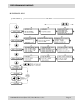
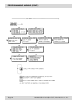
PROGRAMMING FLOW CHART Page 28 120-200-350 © 1993 (Rev 5/97) Max Machinery, Inc.
MICROSOFT QUICK BASIC PROGRAM MICROSOFT QUICK BASIC PROGRAM REM EQUIPMENT: REM COMPUTER WITH A RS-232 STANDARD SERIAL INTERFACE REM RS-232 TO RS-485 COMMUNICATIONS CONVERTER REM RS-232 CONFORMING TO EIA RS-232 RS-232D STANDARD REM RS-485 CONFORMING TO EIA RS-485 STANDARD, DIFFERENTIAL, REM HALF DUPLEX, MULTI-DROP PROTOCOL REQUIRING A TOTAL OF REM TWO WIRES.
MICROSOFT QUICK BASIC PROGRAM PRINT PRINT “ 1 = PORT 1” PRINT “ 2 = PORT 2” PRINT : PRINT “ PICK COMMUNICATION PORT OPTION - “: SELECT$ = INPUT$(1) REM CHECK FOR VALID KEY PORTSEL = VAL(SELECT$): IF PORTSEL = 0 OR PORTSEL > 2 THEN GOTO PORT ON PORTSEL GOSUB PORT1, PORT2 GOSUB SETCOMM RETURN PORT1: REM*****SET PORT 1 ADDRESS***** COMPORT$ = “COM1:”: PT = &H3FC: PT1 = &H3FD RETURN PORT2: REM*****SET PORT 2 ADDRESS***** COMPORT$ = “COM2:”: PT = &H2FC: PT1 = &H2FD RETURN SETCOMM: REM*****ASSEMBLE COMM$***** COM
MICROSOFT QUICK BASIC PROGRAM IF A$ = “E” THEN EXITFLAG = 1 RETURN END IF REM*****BUILD CHECKSUM FOR BUFFER***** BUFF$ = HEADER$ + A$ Y = 0 FOR X = 2 TO LEN(BUFF$) Y = Y + ASC(MID$(BUFF$, X, 1)) NEXT X Y = Y MOD 256: CS$ = HEX$(Y) IF LEN(CS$) = 0 THEN CS$ = “00” IF LEN(CS$) = 1 THEN CS$ = “0” + CS$ BUFF$ = BUFF$ + CS$ LOCATE , , 1: PRINT PRINT : PRINT “ COMMAND SENT = “; BUFF$ REM*****SEND BUFFER OUTPUT***** CLOSE OPEN COMM$ FOR RANDOM AS #1 OUT PT, 11 PRINT #1, BUFF$ DO A = INP(PT1) - (INP(PT1) MOD 96) LOO
HP ROCKY MOUNTAIN BASIC PROGRAM HP ROCKY MOUNTAIN BASIC PROGRAM 12 ! 13 ! EQUIPMENT: 14 ! 15 ! HP9000 MODEL 310 COMPUTER 16 ! 18 ! HP98626 SERIAL INTERFACE, SELECT CODE = 9 19 ! 21 ! RS-232 TO RS-485 COMMUNICATIONS CONVERTER 22 ! RS-232 CONFORMING TO EIA RS-232-D STANDARD 23 ! RS-485 CONFORMING TO EIA RS-485 STANDARD, DIFFERENTIAL, HALF DUPLEX, 24 ! MULTI-DROP PROTOCOL REQUIRING A TOTAL OF TWO WIRES.
HP ROCKY MOUNTAIN BASIC PROGRAM 74 75 76 78 79 80 81 82 83 84 85 86 87 88 89 90 91 92 93 94 97 98 99 100 101 102 104 105 106 108 109 110 111 112 113 114 115 116 117 118 119 120 121 122 123 131 132 133 135 136 137 138 139 140 I=I+1 PRINT Return dat$(I); UNTIL Return_dat$(I)=CHR$(13) ! FIND END OF DATA CARRIAGE RETURN Send more$=”Y” DISP “DO YOU WANT TO SEND MORE DATA Y/N, DEFAULT = “;Send_more$; LINPUT “ “,Variable$ IF LEN(VariableS) THEN Send_more$=Variable$ END IF CLEAR SCREEN IF Send_more$=”Y” THEN Send_
HP ROCKY MOUNTAIN BASIC PROGRAM 149 150 152 162 167 168 169 170 171 172 173 174 175 176 177 178 179 180 181 182 183 184 185 187 188 189 190 191 192 193 194 195 196 197 198 199 200 201 202 203 204 205 206 207 208 209 210 211 212 213 214 215 216 217 SUB RS485(Id_number$,Command$,Unit_parity$,INTEGER Baud_rate,Return_dat$(*) ) ! !*******************RS485 PORT INTERFACE************************ ! INTEGER Rs232_sc,I,Bytes,String_length,Position,Dec_total,Parity_enable INTEGER Unit_parity,Stop_bit,Loop_num DIM Ou
HP ROCKY MOUNTAIN BASIC PROGRAM 218 219 220 221 222 223 224 225 226 227 228 229 230 231 232 233 234 235 236 237 238 239 240 241 242 243 244 245 246 247 248 249 250 251 252 253 256 257 258 259 262 263 264 265 266 267 268 269 270 271 272 273 274 275 Hex_value$=DVAL$(Dec total,16) Checksum$=Hex_value$[7] ! !***********************SEND DATA****************************** ! PRINT “THE OUTPUT IS = >”;Output_format$; PRINT Checksum$ OUTPUT Rs232_sc;”>”&Output_format$&Checksum$&CHR$(13)! SEND MESSAGE ! !***********
HP ROCKY MOUNTAIN BASIC PROGRAM 276 277 278 279 280 281 282 283 284 285 286 287 288 289 290 291 292 293 294 295 296 297 298 299 300 301 302 303 PRINT “” SELECT Error_num CASE 1 PRINT “INVALID COMMAND WAS SENT” CASE 2 PRINT “COMMUNICATION CHECKSUM ERROR” CASE 3 PRINT “BUFFER OVERRUN ERROR” CASE 5 PRINT “DATA FORMAT ERROR” CASE 8 PRINT “PARITY OR FRAMING ERROR” CASE 10 PRINT “IN RUN MODE, COMMAND NOT ALLOWED” CASE 12 PRINT “IN PROGRAM MODE, COMMAND NOT ALLOWED” CASE 13 PRINT “MODE ALREADY ACTIVE.