
Installation Guide

18
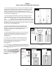
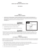
STEP 12
LIFT START UP / FINAL ADJUSTMENTS
DURING THE START-UP PROCEDURE, OBSERVE ALL OPERATING COMPONENTS AND CHECK FOR PROPER
INSTALLATION AND ADJUSTMENT. DO NOT ATTEMPT TO RAISE VEHICLE UNTIL A THOROUGH OPERATIONAL
CHECK HAS BEEN COMPLETED.
1. Apply white lithium grease or equivalent to the inside of the columns where the slide blocks glide.
2. Test the power unit by pressing the push-button switch. Raise the lift a few inches and check all hose connections for
leaks. If the motor gets hot or sounds peculiar, stop and check all electrical connections.
3. Raise the lift to it’s maximum height o the oor until the lift head stops.
4. Lower the lift down below the rst safety stop.
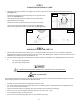
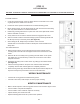
1. With the lift in an elevated position, the hoses connected and the oil reservoir full, loosen the bleeder screws
located at the top of each hydraulic cylinder using an allen wrench. Do not completely remove the bleeder screws.
Watch and listen for trapped air escape the cylinders and uid begins to weep from the screw area. Once steady
uid appears, re-tighten the bleeder screw and cleanup excess oil.
(See gure 19)
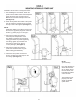
STEP 11
BLEEDING THE CYLINDERS
Bleed Screw
Fig. 19
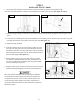
The lift will move down when bleeding, make sure all equipment, personnel,
hands and feet are clear before starting bleeding procedure.
2. Repeat Bleeding proceedure on opposite cylinder.
3. Press the lowering handle on the power unit until the lift lowers
completely to the oor.
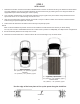
DO NOT use lift if an unlevel lifting condition occurs at the arm pad locations that is greater than 3.5" (89mm). If an
unbalanced condition occurs, follow the bleeding instructions shown on this page or consult Technical Support. The lift
must be re-leveled, shimmed and bled each time the lift is reinstalled. Failure to follow these instructions can result in
serious injury or death.
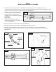
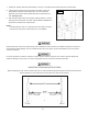
STEP 10
INSTALLING THE SAFETY RELEASE LATCH
SEE PAGE 30