
Installation Guide

16
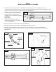
STEP 8
HYDRAULIC POWER UNIT SET UP
STEP 7
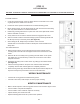
CONNECTING HYDRAULIC LINES
Female Quick
Disconnect
Fitting
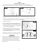
Install the Female Quick Disconnect ttings to the opposite end of
each hose. (See gure 17)
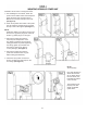
Recheck all tting connections to make sure they are properly
tightened before proceeding.
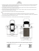
Position the power unit stand at the front or rear of the vehicle.
Connect the Female Quck Disconnect tting to the Male Quick
Disconnect located at the bottom of each column. (See gure 18)
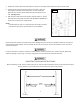
Fig. 16
3/8 NPTF Hose
Fittings
Fig. 18
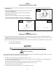
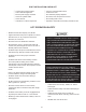
1. Fill the power unit reservoir with 7 quarts (6.6 L) of AW-32 hydraulic oil or Dexron III or VI automatic transmission
uid. Make sure the funnel used to ll the power unit is clean. After bleeding the cylinders, check the oil level to see if
additional oil is needed to ensure the reservoir is full.
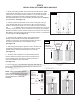
2. The lift should be plugged into a dedicated circuit with a 20 amp circuit breaker. The standard power unit for this lift
is:
US: 110V, 60Hz, single phase
CE: 230V, 50Hz, single phase
ALL WIRING MUST BE PERFORMED BY A CERTIFIED ELECTRICIAN ONLY.
RISK OF EXPLOSION
This equipment has internal arcing or parts that may spark and should not be exposed to ammable vapors. The motor
should not be located in a recessed area or below oor level.
• DO NOT run power unit without oil. Damage to pump can occur.
• The power unit must be kept dry. Damage to power unit caused by water or other liquids such as detergents, acid
etc., is not covered under warranty.
• Improper electrical hookup can damage the motor and will not be covered under warranty.
• Motor can not run on 50hz without a physical change in the motor. (US - only)
• Use a separate breaker for each power unit.
• Protect each circuit with a time delay fuse or circuit breaker. (US-only)
1.
Thread one end of the 3/8 NPT hose ttings into one of the top ports of the Flow Divider. Do this with both hoses.
(See gure 16)
Fig. 17