
Installation Guide

13
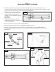
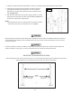
STEP 5
SITE LAYOUT
1. Determine the location of where the lift will be installed based on the size of vehicles servicing. The dimensions shown below
are rough guidelines. "Dry-t" the vehicles intended to be serviced in the bay by referring to the ALI Lifting Point Guide for
appropriate lift points before nalizing the column spacing.
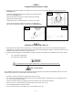
2. Once a location is determined, use a carpenters chalk line to layout a grid for the post locations. Keep all dimensions and
squareness within 1/8" or malfunctioning of the lift can occur.
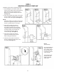
3. After the post locations are properly marked, use a chalk or crayon to make an outline of the columns on the oor at each
location using the post base plates as a template.
4. Double check all dimensions and make sure that the layout is perfectly square.
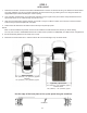
NOTE:
Wide or narrow installation is possible. The lift can be installed at a width that suits the vehicles you will be raising.
You may even choose to install additional anchors at varied column positions for adaptability to multiple vehicle congurations.
5. Recommended bay dimensions 20' deep and 14' wide.
6. Clearance around lift should be 5”. Clearance above lift must exceed height of top of raised vehicle.
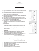
Sport compacts
105" (2667mm) - 115" (2921mm) Typical
Mid size
110" (2794mm) - 120" (3048mm) Typical
Light duty / sport trucks
115" (2921mm) - 120" (3048mm) Typical
Full size trucks
120" (3048mm) - 135" (3429mm) Typical
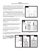
Use the edge of the base plate to line up the posts along the chalk line.
Chalk line