
Installation Guide

12
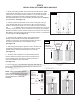
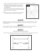
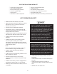
NOTE:
*(Flow Divider)
Pay close attention to
which side the bolts
are on. When facing
the ow divider, the
bolt heads should be
on the left side.
The lift will not work
properly if the ow
divider is installed
upside down.
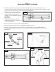
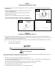
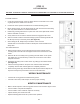
Assemble cart as shown in the gures below:
1. After installing the cart wheels, attach the
power unit and rubber Power Unit Dampener
pad to the power unit cart using the (4)
M8x20 mm Hex Bolts and Nylon lock nuts.
(See gure 6)
2. Attach the Hydraulic Flow ivider to the power
unit cart using the (4) M8x 20 mm hex bolts
and nylon lock nuts supplied. (See gure 7)
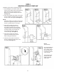
NOTE:
Install ow divider so that when facing it from
the front, the (2) plastic plugs are on the left
and the (1) plastic plug is on the right.*
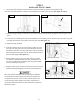
3. Remove the plastic plug from the
lower left port stamped "IN" on the
ow divider. Install the long 90° Elbow
Fitting (P/N 5550170). When tightening
the Fitting, tighten by hand rst and
then using a wrench turn approx.
3 turns past tight. (See gure 8)
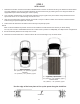
4. Remove the plastic plug from the
power unit and attach the Long 90°
Elbow Fitting (P/N 5550074).
5 Attach the short power unit hose as
shown. DO NOT use teon tape on the
JIC ttings. (See gure 9)