
Installation Guide

11
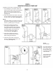
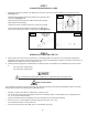
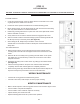
Remove the 6mm allen bolt and install the
Cylinder Fittings. Asssemble all ttings
together, including quick disconnect,
preferably in a vice. Install tting assembly
into cylinder.
(See gure 2)
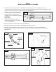
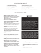
STEP 3
INSTALLING HYDRAULIC CYLINDERS
Fig. 1
Fig. 4
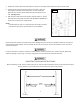
Install the column wheels (P/N 5575061) using M8x55 hex head bolts (P/N 5530377) and M8 nylon lock nut
(P/N 5535001) onto each column. Turn the columns over and lay them down with the open side up. Slide the lift head
to the top of the post. Remove the cylinder from the post. (See gure 1)
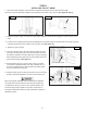
Slide the tting assembly through the
access hole located on the backside of the
columns. (See gure 3)
Slide the Lift Head until it rests rmly on the Baseplate. Stand the column up.
1.
2.
4.
3.
Fig. 2
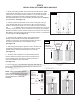
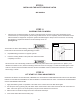
Install the Column Handles (P/N 5505071) with M10 x 25 Hex Head Bolts (P/N 5530738) with M10 Washers
(P/N 5545200) and Post Straps Assemblies (P/N 5601487 ) with M10 x 40mm hex bolts and M10 nylon lock nuts.
(See gure 5)
6.
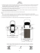
Slide the cylinders through the lift head tube. (See gure 4)
P/N 5505071
4
P/N 5530738
4
P/N 5535013
4
P/N 5530302
4
P/N 5550209
1
P/N 5550076
1
P/N 5550077
1
P/N 5550014
1
Cylinder
Lift Head
5.
Fig. 5
Fig. 3Fig. 3
Fitting Assembly