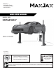
MaxJax™ 5240 Willis Road Theodore, AL 36582 844-629-5291 M6K USER MANUAL MODEL: M6K PORTABLE MID-RISE LIFT 6,000 POUND CAPACITY Patent No. US 8.256.577 B2 Patent No. US 9.150.395.B2 August 2020 P/N# 5900228 Reference ANSI/ALI ALIOM safety requirments for installation and service of automotive lifts before installing lift. PLEASE READ THE ENTIRE CONTENTS OF THIS MANUAL PRIOR TO INSTALLATION AND OPERATION.
IMPORTANT NOTICE 1. Read this manual thoroughly before installing, operating, or maintaining this lift. 2. This lift is designed for indoor use only, and should not be installed in a pit or depression. 3. The floor on which the lift is to be installed must be 4" (101mm) minimum thickness concrete, with a minimum compressive strength of 3000 psi (20 MPa) and reinforced with steel bar. 4. The lifts have specific electrical requirements as described in the Installation Instructions section of this manual. 5.
IMPORTANT SAFETY INSTRUCTIONS READ THESE SAFETY INSTRUCTIONS ENTIRELY Do not attempt to install this lift if you have never been trained on basic automotive lift installation procedures. Never attempt to lift components without proper lifting tools such as a forklift or crane. Stay clear of any moving parts that can fall and cause injury. 1. READ ALL INSTRUCTIONS. 2. READ AND UNDERSTAND all safety warning procedures before operating lift. 3. KEEP AREA WELL LIGHTED. 4. WARNING! RISK OF EXPLOSION.
21. ONLY TRAINED OPERATORS should operate this lift. All non trained personnel should be kept away from work area. Never let non trained personnel come in contact with, or operate lift. 22. USE LIFT CORRECTLY. Use lift in the proper manner. Never use lifting adapters other than what is approved by the manufacturer. 23. DO NOT override self closing lift controls. 24. REMAIN CLEAR of lift when raising or lowering vehicle. 25. CLEAR AREA if vehicle is in danger of falling. 26.
SAVE THESE INSTRUCTIONS OWNER / EMPLOYER RESPONSIBILITIES • Shall ensure that lift operators are qualified and that they are trained in the safe use and operation of the lift using the manufacturer’s operating instructions and regional requirements. • Shall establish procedures to periodically inspect the lift in accordance with the lift manufacturer’s instructions and regional requirements.
Failure to follow danger, warning, and caution instructions may lead to serious personal injury or death to operator or bystander or damage to property. Please read entire manual prior to installation. Do not operate this machine until you read and understand all the dangers, warnings and cautions in this manual.
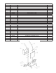
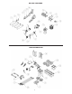
M6K PRODUCTION ITEM No.
MAXJAX PARTS BAG ITEM No. PART NUMBER DESCRIPTION QTY 1 5505071 M6K SAFETY PIN ASSEMBLY 4 2 5746491 MAXJAX LIFT HEAD RELEASE PIN 4 3 5505001 SAFETY CLEVIS PIN 2 4 5530738 HHB M10 X 1.5 X 25 4 5 5545200 WASHER M10 X Ø18 SL 4 6 5530377 HHB M8 X 1.25 X 55 4 7 5550077 FTG -06 NPTF X -06 NPTF, HEX NIPPLE 2 8 5550076 FTG 45° ELB -06 NPTF X -06 NPTF 2 9 5535001 NUT M8 X 1.
MAXJAX PARTS BAG MAXJAX PARTS BOX 9
INSTALLATION INSTRUCTIONS TOOLS REQUIRED • • • • • • • • • • • • Rotary Hammer Drill or Similar 7/8" (22mm) Masonry Bit Hammer 4 Foot Level (1.5 M) Open End Wrench Set: Metric Socket and Ratchet Set: Metric Hex Key / Metric Allen Wrench Set Large Crescent Wrench Large Phillips Screwdriver Chalk Line Medium Phillips Screwdriver Tape Measure: 25 Foot (7.5 M) Minimum IMPORTANT NOTICE These instructions must be followed to ensure proper installation and operation of your lift.
STEP 3 INSTALLING HYDRAULIC CYLINDERS 1. Install the column wheels (P/N 5575061) using M8x55 hex head bolts (P/N 5530377) and M8 nylon lock nut (P/N 5535001) onto each column. Turn the columns over and lay them down with the open side up. Slide the lift head to the top of the post. Remove the cylinder from the post. (See figure 1) 2. Remove the 6mm allen bolt and install the Cylinder Fittings. Asssemble all fittings together, including quick disconnect, preferably in a vice.
Assemble cart as shown in the figures below: 1. After installing the cart wheels, attach the power unit and rubber Power Unit Dampener pad to the power unit cart using the (4) M8x20 mm Hex Bolts and Nylon lock nuts. (See figure 6) 2. Attach the Hydraulic Flow ivider to the power unit cart using the (4) M8x 20 mm hex bolts and nylon lock nuts supplied.
STEP 5 SITE LAYOUT 1. Determine the location of where the lift will be installed based on the size of vehicles servicing. The dimensions shown below are rough guidelines. "Dry-fit" the vehicles intended to be serviced in the bay by referring to the ALI Lifting Point Guide for appropriate lift points before finalizing the column spacing. 2. Once a location is determined, use a carpenters chalk line to layout a grid for the post locations.
STEP 6 INSTALLATION OF POWER DROP ANCHORS 1. Before proceeding, double check location and measurements, make certain that the base plates of each column are aligned with the chalk/ crayon lines. The concrete must be minimum of 4" (101mm) thick with a minimum compressive strength of 3000 psi (20 MPa). FOLLOW PROCEEDURE EXACTLY FOR PROPER FITTING AND ALIGNMENT OF ANCHORS. (See figure 10) Fig. 10 2. Use the squared-up base plate on the column as a guide.
7. Install both columns with bolts and washers to anchors, check plumb and measurements as shown below. 8. If shimming is required, insert the shims as necessary under the base plate so that when the provided 5/8 x 2" anchor bolts are tightened, the columns will be plumb both side to side and front to rear. (See figure 15) Fig. 15 9. With the shims and anchor bolts in place, tighten all 5/8 x 2" anchor bolts tight to the base plate. DO NOT USE AN IMPACT WRENCH or the anchors could become compromised.
STEP 7 CONNECTING HYDRAULIC LINES 1. Thread one end of the 3/8 NPT hose fittings into one of the top ports of the Flow Divider. Do this with both hoses. (See figure 16) 3/8 NPTF Hose Fig. 16 Install the Female Quick Disconnect fittings to the opposite end of Fittings each hose. (See figure 17) Recheck all fitting connections to make sure they are properly tightened before proceeding. Position the power unit stand at the front or rear of the vehicle.
STEP 9 INSTALLING THE LIFT ARMS 1. Place the lift arm assembly on the lift heads. Install the lift head pins into the lift head and through the holes in the arm assembly. Install the quick release pin into place on the arm pin. (See figure 20 and 21) Fig. 20 Fig. 21 Quick Release Pin 1. Raise the lift high enough so that the arm gear stops. Attempt to automatically engage the restraint gears on the arms. 2.
STEP 10 INSTALLING THE SAFETY RELEASE LATCH SEE PAGE 30 STEP 11 BLEEDING THE CYLINDERS 1. With the lift in an elevated position, the hoses connected and the oil reservoir full, loosen the bleeder screws located at the top of each hydraulic cylinder using an allen wrench. Do not completely remove the bleeder screws. Watch and listen for trapped air escape the cylinders and fluid begins to weep from the screw area. Once steady fluid appears, re-tighten the bleeder screw and cleanup excess oil.
POST INSTALLATION CHECK OFF Columns are properly leveled Anchor bolts are tightened Electric power supply confirmed Check for hydraulic leaks Check oil level Lubrication of critical components Check for overhead obstructions Lift arms are level Arm restraints properly adjusted All screws, bolts, and pins are secured Surrounding area is clear Operation, maintenance and safety manuals on site LIFT OPERATION SAFETY • NEVER exceed rated capacity of 6,000-lbs.
STEP 13 LIFT OPERATION BE SURE TO READ ALL SAFETY TIPS PRIOR TO OPERATING LIFT. FAILURE TO DO SO MAY RESULT IN SERIOUS INJURY OR DEATH. TO RAISE VEHICLE: 1. Center the vehicle between columns. Adjust vehicle front-to-back so the center of gravity falls in the middle of the columns. 2. Position lift contact pads at manufacturers recommended lifting points. 3. Before raising vehicle, be sure all personnel are clear of the lift and surrounding area. Pay careful attention to overhead clearances. 4.
STEP 14 LIFT REMOVAL 1. Depress the lowering valve on the power unit. 2. Ensure that the lift is lowered all the way to the ground and hydraulic pressure is relieved. 3. Disconnect the power unit from the power source and / or ensure that the power to the circuit is shut off to prevent accidental powering on of the lift while disassembling. 4. With a cloth in hand to collect weaping fluid, disconnect the cylinder hoses from the cylinder. Hoses can be coiled and stored on the power unit cart.
TROUBLESHOOTING GUIDE BE SAFE: DO NOT OPERATE OR REPAIR EQUIPMENT WITHOUT READING THIS MANUAL AND THE IMPORTANT SAFETY INSTRUCTIONS. KEEP THIS OPERATION MANUAL NEAR THE LIFT AT ALL TIMES. MAKE SURE THAT ALL USERS READ AND UNDERSTAND THIS MANUAL. LIFT WILL NOT RAISE (BUT MOTOR RUNS) POSSIBLE CAUSE 1. 2. 3. 4. 5. 6. 7. 8. 9. 10.
MOTOR WILL NOT RUN POSSIBLE CAUSE 1. 2. 3. 4. 5. Panel circuit breaker flipped, (5,2,1,3,4) Motor burned out, (1,2,3,6,4) Voltage to motor incorrect, (2,1) CE USERS ONLY: Internal motor circuit breaker flipped (7) CE USERS ONLY: Fuse protecting contractor has blown (8) REMEDY INSTRUCTIONS 1. Check for correct voltage. Compare supply voltage with voltage on motor name tag. Check that the wire is sized correctly. N.E.C. table 310-12 requires AWG 10 for 20 Amps. Check wall outlet voltage and wiring.
WILL NOT RAISE ONLY UNDER LOADED CONDITION POSSIBLE CAUSE 1. 2. 3. 4. 5. 6. 7. 8. 9. 10. Air in oil, (4,1,2,3) Cylinder / lift head binding, (5) Cylinder leaks internally, (5) Lift overloaded, (6,5) Lowering valve leaks, (7,1,8,5,9) Motor runs backwards, (10,12,9) Pump damaged, (5,9) Pump won’t prime, (1,2,3,4,11,5,9) Relief valve leaks, (8,5,9) Voltage to motor incorrect, (10,12,5) REMEDY INSTRUCTIONS 1. 2. 3. 4. 5. 6. 7. 8. 9. 10. 11. 12. Check oil level.
5240 Willis Rd Theodore, AL USA Tel: (844) 629-5291 maxjax.com TECHNICAL SERVICE BULLETIN MODELS: MAXJAX M6 AND M6K SUBJECT: HYDRAULIC HOSE REPLACEMENT The purpose of this Technical Service Bulletin is to describe the new Short Hydraulic Hose used for connecting the Power Unit to the Hydraulic Flow Divider.
Safety Latch Release 1. Install the Safety Latch Release on the Safety Weldment Pin. 2. Slide the Retaining Ring on to the Safety Weldment Pin. 3. Slide the Safety Release Assembly onto the Safety Release Plate on the Post. 4. Insert the Clevis Pin through the Torsion Spring. 5. Insert the Clevis Pin through the Safety Weldment and the Release Plate. 6. Insert the second Torsion Spring on to the Clevis Bolt. 7. Attach the Cotter Pin to the Bolt. 8. Attach the Safety Cover with two M6 Screws.
844-629-5291 31
844-629-5291 32