SETU ATA211G System Manual
SETU ATA211G VoIP-FXS-GSM Adaptor System Manual
Documentation Disclaimer Matrix Comsec reserves the right to change, at any time, without prior notice, the product design, specifications, components, as engineering and manufacturing may warrant. This is a general documentation for all models/configurations of the product. The product may not support some of the features/facilities described in this document.
Contents Introduction..................................................................................................................................................... 1 Welcome ............................................................................................................................................................. 1 About this System Manual ..................................................................................................................................
Features of SETU ATA211G ....................................................................................................................... 105 Call Hold .......................................................................................................................................................... 105 Making a Second Call ..................................................................................................................................... 106 Call Transfer .....................
CHAPTER 1 Introduction Welcome Thank You for choosing SETU ATA211G! This product is designed to give you the highest performance, combined with real ease of use. We hope you will make the optimum use of intelligent, intuitive, feature-packed VoIP Phone Adapter. We recommend you to read this document carefully to get acquainted with the product before installing and operating it.
• Configuring Advance Settings: Contains instructions for configuring the more advanced features and facilities of SETU ATA211G. • Features of SETU ATA211G: Describes in detail, the features of SETU ATA211G, along with instructions for configuring and using these features. • System Status: Displays the status indicators of system parameters like SIP, Mobile, Network (LAN and WAN), etc and details of the System Firmware.
Some of the terms specific to this manual that you will encounter frequently are defined below: Term Usage in the document Admin A person who install, configure and maintains SETU ATA211G. Admin can also be the user. Admin has full accessibility of the system. User A person who uses SETU ATA211G. User has limited access to the system. Caller/Calling Party A person who makes calls. Callee/Called Party A person who receives the calls. Transferor A person who transfers the calls.
4 Matrix SETU ATA211G System Manual
CHAPTER 2 Know Your SETU ATA211G Overview ATA211G is a VoIP Analog Telephone Adapter used as a SIP-FXS-Mobile gateway. It allows you to make and receive voice calls over IP Network as well as PSTN network using conventional telephone instrument. ATA211G can be used in Residence, SOHO, Corporate Offices, Industries, Workshops, etc. ATA211G can be used to make voice calls to remotely located branch offices of an enterprise using Internet network.
Ports and Connectors Port Name Connector Description 12V DC DC Jack Power Adapter LAN RJ45 To connect a standalone computer or a LAN Swtich. WAN RJ45 To connect to the IP network over a DSL Modem or Router or a LAN Swtich FXS RJ11 To connect a standard telephone instrument or a PBX. SIM SIM holder To connect to GSM network. Antenna SMA (Male) To connect Mobile port antenna.
POWER FXS GSM SIP1 SIP2 SIM SIM Matrix SETU ATA211G System Manual ANTENNA 7
Applications of SETU ATA211G 1. Residential Application: Home users can use ATA211G to make low-cost international calls to family, friends and relatives. IP Network FXS Broadband Modem/Router ATA211G LAN Mobile Proxy GSM Network 2. SOHO Application: Small Office owners can use ATA211G to make low-cost calls to their overseas customers, employees, suppliers, etc.
3. Business Application: Corporate Offices can use ATA211G to make low-cost international calls to their overseas customers, employees, suppliers, etc. IP Network Proxy FXS1 PBX WAN Broadband Modem/Router ATA211G Switch LAN Mobile GSM Network 4. Peer-to-Peer Call Application: Corporate Offices also use SETU ATA211G to communicate between various branch offices, at no cost.
10 Matrix SETU ATA211G System Manual
CHAPTER 3 Getting Started Preparing for Installation Package Contents SETU ATA211G with Antenna Adaptor 12V, 1.25 Amp (Country Specific) Quick Start and User Card Ethernet Cable (RJ45) CD containing System Manual, Quick Start and User Card Two Screws M 7/30 Two Screw Grips Warranty Card Set External Antenna SMA with Cable • Unpack SETU ATA211G. • Verify the package contents. Contact your vendor/Service Provider/administrator, if any of the above listed items is missing or damaged.
Safety Instructions Take every measure to reduce the risk of fire, electric shock and injury to the person handling this product. • • • • • • • Read all the instructions given in this manual. Always switch off the product, unplug the product from the wall outlet when handling it. Removing covers or opening the system or incorrect reassembly increases the risk of electric shock. Never open the system in power ON condition. Use the adapter provided with the product.
Connecting SETU ATA211G Power Adaptor IP DSL Modem/ Router PC/LAN • Connect a standalone computer/ LAN Switch to the LAN Port of SETU ATA211G using an Ethernet cable. • Connect the WAN Port of SETU ATA211G to the IP Network - a DSL modem or Router or a LAN Switch using the Ethernet cable provided to you. • Connect a telephone to the FXS Port of SETU ATA211G, using a standard telephone cable with an RJ11 plug. POWER FXS GSM SIP1 SIP2 You may also connect a PBX to the FXS port of SETU ATA211G.
• • Remove the SIM Card from the Mobile Handset. Insert the SIM Card in to the SIM Holder of SETU ATA211G. You may change the SIM PIN to the desired value after system installation is completed. You can change the SIM PIN from Mobile Port parameters page of Jeeves. See “Mobile Port” under Basic Settings for instructions. • Insert SIM Card into the SIM holder of the Mobile Port of SETU ATA211G. To do this, • • • • • press the SIM holder lock (the small yellow button).
LED Status Meaning Mobile ON SIM Card is present and or registered with the network. Blinking (100 ms ON-100 ms OFF) SIM Card is absent or de-activated or SIM PIN is faulty or SIM PUK is required Blinking (1 ms ON - 1 ms OFF) SIM Card detected but is not registered with the network OFF ATA211G is powered ON but SIM Card is not detected ON SIP1 is enabled and is registered with the SIP server or 'Active' status of SIP Trunk.
Configuring SETU ATA211G SETU ATA211G provides access to system configuration at two levels: Admin and User. A distinct set of features and facilities can configured at each of these levels. SETU ATA211G can be configured using its Web-based graphic user interface (GUI) and from the phone connected to its FXS port. While the entire system configuration can be done using the GUI, you can configure only certain parameters from the phone.
If required, change the IP Address and the Subnet of the computer. You may also connect the LAN port of SETU ATA211G to a LAN switch. If you connect the LAN port of SETU ATA211G to a LAN Switch, make sure that the IP Address of LAN port of SETU does not conflict with the IP Address of any device on the LAN, and SETU ATA211G is in the same Subnet as the LAN computer.
• In the Login as combo box, select Admin. • In the Password field, enter 1234, the default Admin Password. • Click the Login button. • On successful login, the Admin mode page will open. • The left pane shows the links Basic Settings, Advanced Settings, Supplementary Services, and Status. Basic Settings are sufficient to get your SETU ATA211G into operation. • Click the links to expand. To log in as User, 18 • In the Login as combo box, select User.
Configuring using a Phone You can enter the Admin mode and the User mode using the phone connected to the FXS Port of SETU ATA211G, and change feature settings, and certain network parameters like the IP Address and Subnet Mask of the LAN and the WAN port of SETU ATA211G, select the Connection Type (IP Addressing) by dialing “System Commands” from the phone connected to its FXS port of SETU ATA211G.
20 Matrix SETU ATA211G System Manual
CHAPTER 4 Configuring Basic Settings The Basic Settings enable you to configure SETU ATA211G for basic functions. As Basic Settings cover much of your configuration requirements, you will be able to operate and use the system efficiently, when you configure Basic Settings. To configure Basic Settings, • Click Basic Settings link. The links to the different basic parameters appear on the left pane. There are two ways to configure Basic Settings: • Using the Wizard.
To use the Wizard, • Click the Wizard icon on the top right of your screen. • • The Next button takes you to the next page, saving the changes you made on the current page. The Back button returns you to the previous page. • The More button expands parameters on the page. • The Less button collapses parameters on the page. • The Quit exiting. button allows you to exit the Wizard at any stage, saving changes you made before To use selective configuration, • Click Basic Settings link to expand.
Region 1. Click Region. 2. Click More button to view all parameters on the page. 3. Select Admin Language and User Language. Default: English. SETU ATA211G can display the Admin and User pages of the GUI, Jeeves, in the following languages: • English • Italian • Spanish • French • German • Portuguese All the Admin and User Pages of the GUI will appear in the language you selected, when you login again as Admin or User.
When you reset SETU ATA211G to factory defaults, the Ring you selected will not be set to default. 6. To synchronize Date and Time of SETU ATA211G with that of the country where it is installed, select Time Zone from the drop down list. Default: (GMT+05:30) Kolkata, Chennai, Mumbai, New Delhi. 7. To use a public internet time server for date and time synchronization, select an internet based time server as NTP Server.
SIP Trunks SETU ATA211G supports three SIP trunks, which may be configured as Proxy or Non-Proxy, i.e. Peer-to-Peer trunks. You may register with three different ITSPs and use their services. 1. Click the SIP link. The parameters of SIP Trunk 1 appear on your screen. 2. Click More button to view all parameters of SIP Trunk 1 on this page.
Trunk Settings 1. Select the SIP Trunk Enable check box to use the SIP Trunk. Default: Disabled. You may disable the SIP trunk, if you do not want to include it in Call Routing. 2. Select SIP Trunk Mode according to your installation. Default: Peer-to-Peer. • Select Proxy, if you want to register this SIP trunk with an ITSP or a Registrar Server. • Select Peer-to-Peer, if you want to use the trunk for Peer-to-Peer (non-proxy) calls.
• The Peer-to-Peer Numbers table opens in a new window. • You can configure as many as 500 number strings, which are stored against an Index number. • In the Number field, enter the peer-to-peer number string - prefix or entire number - that will be dialed. The number string must not exceed 24 characters. Default: Blank. If the number to be dialed out is , for example, 123@abc.com, you must enter 1234 in this field.
For example, if the peer-to-peer number to be dialed out is 123@abc.com, enter abc.com as Destination Address. If the number is 1234@ 192.168.1.197, enter 192.168.1.197 as the Destination Address. The Destination Address can also be in the form of Address:Port number. • Click Submit to save entries. • Close the window. 3. Enter the SIP ID. This is the ID which remote parties will use to call this SIP Trunk. Default: Blank. The SIP ID may be a number or text consisting of a maximum of 40 characters.
• In the Outbound Proxy Server Address: Port field, enter the IP address or domain name of the Outbound Proxy Server and the number of the Outbound Proxy Server’s Listening Port for SIP. The Server Address may consist of maximum 40 characters. Default: Blank. The valid range for the port is 1024-65534. Default: 5060. 10. To add ‘rinstance’ in the REGISTER Message, keep this feature enabled. Default: Disabled.
• Route To FXS: The system will place all calls received on the SIP Trunk on the FXS port. The phone connected to the port will start ringing for the duration of the Ring Timer (default: 45 seconds). If the call is not answered within this timer, it will be rejected. This is also the default routing option. • Route to fixed destination number through Mobile: The system will place all calls received on the SIP Trunk to a Fixed Destination Number through the Mobile port.
4. If you want to Authenticate Incoming Calls on SIP, that is, you want to allow incoming calls only after callers have authenticated themselves. You can select: • PIN: Select this option to authenticate callers with a unique PIN. • Digest: Select this type of authentication if you want to allow incoming calls on the SIP Trunk only after callers have authenticated themselves with their User ID and Password. Default: Disabled. If you have selected PIN, you must configure the PIN Authentication Table.
• Enter the PIN to be authenticated against each Index in the Table. The PIN number can have a maximum of 4 digits. The characters allowed are: 0-9,*, # • If you have finished entering, click Submit to save. • Close the window. See “PIN Authentication”. If you enable Digest Authentication, you must configure the Digest Authentication Table. To do this, 32 • Click the arrow icon. • The Digest Authentication Table page opens in a new window.
• Enter the User ID to be authenticated along with its corresponding Password against each Index in the Table. The User ID may be a maximum of 40 characters. The User Password may be a maximum of 16 characters. • If you have finished entering the User IDs and their corresponding User Passwords in this Table, click Submit. • Close the window. To know more about this feature, see “Digest Authentication”. Vocoders 1. Select Vocoders in the order of preference from the multiple selection box.
Advanced 1. Select the default SIP Transport for outgoing SIP messages from the following options: • UDP: Outgoing messages are transported using UDP. • TCP: Outgoing messages are transported using TCP. • TCP (Fallback to UDP): TCP is used for outgoing messages. However, if the TCP connection fails, the system will attempt to send the message again over UDP. Default: UDP To use TCP or TCP (Fallback to UDP), you must enable SIP over TCP in the “System Parameters” page. 2.
ANT is also used when SETU ATA211G is deployed for networking between PBXs at multiple sites, and “Multi Stage Dialing” is required. To use ANT, select the check box and configure the Automatic Number Translation Table. To do this, • Make a list of numbers that need to be modified before being dialed out from this SIP trunk. Make a list of the corresponding modified numbers that the system should substitute the dialed numbers with. • Click the arrow icon.
• In the Dialed Number column, enter the numbers that need to be modified when dialed out from this SIP trunk. • In the Substitute Number column, enter the numbers which the system should dial out in place of the dialed numbers. Make sure you enter a Dialed Number and its corresponding Substitute Number at the same Index number in the table. For example, if you entered 001 as Dialed Number at Index 01, you must enter its corresponding Substitute Number 1 also at Index 01.
• In the On Time field, set the time for which the DTMF digit should remain on, when the digit is dialed out by the system. The DTMF On Time may be 100 or 150 or 200 milliseconds. Default: 100 milliseconds. • In the Off Time field, set the time for which system should wait before dialing the successive DTMF digits. The DTMF Off Time may be 100 or 150 or 200 milliseconds. Default: 100 milliseconds. 10.
Mobile Port SETU ATA211G supports a Mobile Port. Insert the SIM card in the SIM holder to get your ATA211G connected to the GSM network. To configure the Mobile Port parameters, 1. Click Mobile. 2. Click More button to view all Mobile parameters on this page. General 1. Select the Enable check box to use the Mobile Port. Default: Disabled. You may disable the Mobile Port, if you do not want to include it in Call Routing.
2. You can assign a Name to the Mobile port, which will be displayed to the called party (if the instrument of the called party supports display name functionality). The name you assign may consist of a maximum of 24 characters. Default: Blank. Incoming Call 1. Select an appropriate Incoming Call Routing option for the Mobile Port. You may select: • Reject Incoming Calls: Select this option if you want ATA211G to reject the incoming calls on the Mobile port.
• Answer the call, collect number & route as per incoming call route selection: Select this option if you want the system to first answer the call on the Mobile Port, play dial tone to the caller, collect the digits dialed by the caller and route the call as per the Incoming Call Route you select: SIP1, SIP2, SIP3 or Dialed Number Table. If you select this option, select the Incoming Call Route. • Route to FXS.
• The Dialed Number Table opens in a new window. For each Index number, • Enter the desired Number you want to store in the table. The number must not exceed 24 characters. • For the number you entered, define the Minimum Digits, which the system should wait to receive before considering it as a valid number. Default: 01. • For the number you entered, define the Maximum Digits, which the system should wait to receive before considering it as End of Dialing. Default: 24.
• Click Submit to save entries and close the window. See “Dialed Number Table”. 2. In the Ring Timer field, set the duration for which the ring should be played on the FXS Port for an incoming call. The range of the Ring Timer is of 01 to 99 seconds. Default: 45 sec. 3. Select the required type of CLI to be displayed on the FXS Port during an incoming call: • Calling Number: Select this option if you want the number of the Calling Party to be displayed as CLI on the FXS Port.
• The PIN Authentication table opens in a new page. • Enter the PIN to be authenticated against each Index in the Table. The PIN number can have a maximum of 4 digits. The characters allowed are: 0-9,*, # • If you have finished entering, click Submit to save. • Close the window. See “PIN Authentication”.
1. Select the Automatic Number Translation check box, if you want to apply this feature on the Mobile port. Default: Disabled. Automatic Number Translation (ANT) enables you to modify or translate the dialed number into another number. ANT is useful when you need to modify or replace a few digits of the dialed number with other digits, before the system dials out the number.
• The Automatic Number Translation table opens in a new window. In this table, you can store as many as 24 Dialed Numbers and their corresponding Substitute Numbers, at Index Numbers 01 to 24. • In the Dialed Number column, enter the numbers that need to be modified when dialed out from the Mobile Port. • In the Substitute Number column, enter the numbers which the system should dial out in place of the dialed numbers.
The Mobile Network Selection feature of SETU ATA211G enables you to select the GSM network of your choice, either automatically or manually. At Power On, ATA211G will automatically locate and register the SIM with the Network that supports the SIM card installed in it. If the SIM fails to register, it will restart the process of network selection on the expiry of the Network Registration Retry Timer. • Automatic: Select this option if you want the system to select the GSM network automatically.
11. You may configure the Pause Timer if you want to insert a delay before dialing the DTMF digits on the Mobile port. The Pause Timer is typically used in Multi-Stage Dialing. Valid range: 1 to 9 seconds. Default: 2 seconds. 12. In the Returned Calls to Original Caller (RCOC) option, enable the type of RCOC you want to set for the Mobile Port. • On Busy: Enable this type if you want to set RCOC when the call is returned if the called party is found busy.
FXS Port SETU ATA211G supports an FXS port. Depending upon your requirement, you can either connect an standard, analog telephone instrument to the FXS port, or interface the FXS port with the FXO port of a PBX. To configure the FXS port parameters, 1. Click FXS. 2. Click More button to view all FXS port parameters on this page. General 1. By default Call Routing is enabled on the FXS port.
You may disable the FXS Port and if you do not want to include it in Call Routing. 2. You can assign a Name to the FXS port, which will be displayed to the called party (if the instrument of the called party supports display name functionality). The name you assign may consist of a maximum of 24 characters. Default: Blank 3. You can assign a Number to the FXS port. In case of Peer to Peer calls this number will be displayed to the called party.
• The Dialed Number Table opens in a new window. In this table, entries are stored at Index numbers from 001 to 100. For each index number, 50 • Enter the desired Number (max. 24 characters) you want to store in the table. • For the number you entered, define the Minimum Digits, which the system should wait to receive before considering it as a valid number. Default: 01.
• At the bottom of the table, select Destination Trunks for dialed numbers that do not match with any of the entries configured in this table, i.e. the No Match Found. For calls made from the FXS port, select the the destination trunk for the option If dialed number does not match with either of the programmed number in the Dialed Number Table & call is made from FXS, route the call through. Default, SIP Trunk 1.
• Enter the PIN to be authenticated against each Index in the Table. The PIN number can be of a maximum of 4 digits. The characters allowed are (0-9,*, #). • If you have finished entering, click Submit to save. • Close the window. To know more about this feature, see “PIN Authentication”. 5. Enable Auto Mobile Fallback check box if you want ATA to automatically route the calls through the Mobile port when the internet (ethernet) link is down and the SIP trunks cannot be used for call routing.
Advanced 1. Select the appropriate Answer Signaling Type on the FXS port. Answer Signaling is required when SETU ATA211G has a PCO/Billing machine connected on its FXS port. When a call is made through SETU ATA211G and the called party answers the call, call maturity signal must be generated on the FXS port of SETU ATA211G so that the PCO/Billing device connected to its FXS port can start billing.
Default: Polarity Reversal. • Open Loop Disconnect Timer: If you selected Open Loop Disconnect, you may set the value of this timer, as required. Default: 500 milliseconds. 3. Select the Subscriber Type for SETU ATA211G. Default: Gateway. When SETU ATA211G is interfaced with a service provider server—ITSP, the Matrix ETERNITY IP-PBX, or any other PBX—that supports supplementary services that require dialing of Flash, like Call Hold, Call Transfer, Call Waiting, etc.
8. If required, you may adjust the Speaking Volume (Transmit) on the FXS port to increase or decrease the volume of your voice being transmitted to the remote party. Select the appropriate Speaking Volume from the drop-down list. Default: 0 db. 9. You may also adjust the Listening Volume (Receive) on FXS port to increase or decrease the volume of the remote party's voice being transmitted to you. Select the required Listening Volume level from the drop-down list. Default: 0 db. 10.
Passwords The system can be programmed by the Administrator or the User, by logging into Jeeves as Admin or User with their respective Passwords. The default Admin and the default User Password are the same, 1234. Since the Admin Login gives you access to configure all the parameters of SETU ATA211G, while the User login has access to only user specific parameters, you may change the default password and use different Passwords for Admin and User Login. The password must not exceed 4 digits.
2. Dial #*** You will get dial tone after successful execution. 3. Replace handset. The Admin password will be set to the default value, if the Default Admin Password when User defaults the ATA? option is enabled in the System Parameters. To avoid this, make sure you disable this option in the “System Parameters”. Changing User Password You can change the User Password only from Jeeves. To change User Password from Admin Mode: 1. Log in as Admin. 2.
3. Click the User Password. 4. Enter the current password in the Old Password field. 5. Enter the new password in the New Password field. 6. Type the new password again for confirmation in the Re-Enter to Confirm field. Restoring Default User Password The User Password is automatically set to the default value whenever you reinstate factory defaults in the system.
Network Parameters 1. Click Network. 2. Click More button to view all Network parameters on this page. Routing Mode • Select Routing Mode, according to your installation scenario as NAT or Bridge. Default: NAT. • Select NAT as Routing Mode, if the LAN and WAN port of SETU ATA are in different network segments.
• Select Bridge as Routing Mode, if the LAN and WAN port of SETU ATA are in the same network segment. Selecting Bridge mode will disable Network Address Translation (NAT) on the WAN port. When you set SETU ATA211G in Bridge Mode, you need not configure the LAN port IP Address and Subnet Mask. The WAN and the LAN port of SETU ATA211G can be accessed with the IP Address of the WAN port. LAN The LAN port of SETU ATA211G is used for connecting a standalone computer or a LAN Switch.
Enter PPPoE User ID (max. 40 characters) and Password (max. 24 characters). You may also enter the PPPoE Service Name (max. 24 characters), if provided. DNS Server DNS stands for Domain Name Server which is used to resolve domain name into IP address. You can select either Static or Automatic. 1. Select Static if you want to configure DNS manually. • Enter Primary DNS Address. • Enter Secondary DNS Address, if available.
• For RTP CoS, define the CoS (priority) bits which will be added in all RTP packets. The range of CoS bits is from 0 to 7. Default: 6. 2. SETU ATA211G will send all SIP messages using SIP QoS setting, enter the SIP DiffServe/ ToS as per your requirement. Valid range is from 00-63, Default: 26 3. SETU ATA211G will send all the RTP packets with RTP QoS setting, enter the RTP DiffServe/ ToS as per your requirement. Valid range is from 00-63, Default: 46 4.
CHAPTER 5 Advanced Settings The Advanced Settings include the features and facilities listed below:: • “System Parameters” • “Called Party Number Table” • “Dialed Number Table” • “Peer-to-Peer Numbers” • “Mobile Emergency Numbers” • “Digest Authentication” • “Daylight Saving Time” • “Static Routing” • “Reinstate Factory Defaults” • “Restart SETU ATA211G” • “Syslog” • “PCAP” • “Software Upgradation” • “Auto Configuration” Matrix SETU ATA211G System Manual 63
System Parameters Certain parameters of SETU ATA211G are applied system-wide and are not specific to a port. These parameters are called System Parameters. To configure System Parameters, 1. Log into Jeeves as Admin with your password. 2. Click the Advanced Settings link on the left pane to expand the links. 3. Click System. The System Parameters page opens. 4. Click the More button to view all the System parameters on this page.
about End of Dialing while dialing minimum or maximum numbers. Valid range: 01 to 99 seconds. Default: 5 seconds. • Transfer Notification Timer: This is the time for which the system will wait for notification of the status of a transferred call, i.e. whether the transfer target is busy, has answered, has disconnected, etc. Refer “Call Transfer” topic to know more. Valid Range: 01-99 secs. Default: 60 seconds.
If you are an ITSP, you may use this flag (disable) to prevent your customers (end users) from setting the Admin Password to default and gaining unrestricted access to system configuration. NAT • STUN (Simple Traversal of UDP through NAT) server facilitates traversing through most NATs, except symmetric NATs. So, if your router has Symmetric NAT, do not configure STUN.
• UDP NAT Keep Alive: When SETU ATA211G is connected behind a NAT router and SIP messages are transported over UDP, NAT Keep Alive messages must be sent to refresh the binding in the NAT router. Select the UDP NAT Keep Alive check box to enable. Default: Disabled. Select the the type of Keep Alive Message to be sent. You may select either REGISTER or NOTIFY. Default: NOTIFY. As Interval, set the time period after which the system should send Keep Alive messages.
By default, SIP over TCP is enabled. If you want to receive SIP messages over TCP keep this option enabled. You must also enable TCP or TCP (Fallback to UDP) on the SIP Trunk. 68 • SIP UDP Port: This is the port on which the SETU ATA211G listens for SIP messages transported over UDP. This port is also used as the source port for sending SIP messages to the remote peer. The valid range for this port is 1024–65534. Default: 5060.
Called Party Number Table Called Party Number Table is used for routing incoming calls on the SIP trunks on the basis of the Called Party Number received, without answering the call. You must configure this table, if you have selected 'Route as per called party number' as the Incoming Call Routing option for the SIP trunk. In the Called Party Number Table, you can store a maximum of 10 numbers. Each number is stored at an Index in the table.
To be considered as a valid number, the number received must be equal to or more than the Minimum digits configured. If the number received matches the Minimum digits but exceeds the maximum digits, the system will strip off the extra digits and route the number. If the incoming CLI does not match with any entry in Called Party Number Table (i.e. the number does not exist in the table, the call will be routed through the destination route for the first entry at Index 001, i.e.
Dialed Number Table Dialed Number Table allows the SETU ATA211G to select the most suitable trunk for outgoing calls on the basis of the number dialed. You must configure this table, if you have selected 'Dialed number based routing' for the FXS Port and the Mobile Port. The Dialed Number Table is a list of numbers or part numbers (which you must configure), with a preferred destination port/trunk for each number: FXS, SIP1, SIP2, SIP3, or Mobile.
• • You can also configure the Destination Route for dialed numbers that do not match with the table by the Source Port. • If the Mobile port is the Source Port, you can route the call through — SIP1/SIP2/SIP3 or FXS. • If FXS port is the Source Port, you can route the call through— SIP1/SIP2/SIP3, or Mobile. You can also restrict dialed numbers that do not match with the table by not selecting any destination route.
4. For each Index number, • Enter the desired Number you want to store in the table. The number must not exceed 24 characters. • For the number you entered, define the Minimum Digits, which the system should wait to receive before considering it as a valid number. Default: 01. • For the number you entered, define the Maximum Digits, which the system should wait to receive before considering it as End of Dialing. Default: 24.
Peer-to-Peer Numbers Calls made between two IP clients without the intervention of a Proxy Server are defined as Peer-to-Peer Calls (P2P calls). P2P call can be made from FXS or Mobile port. As the Peer-to-Peer call application does not require a SIP server, voice communication using this application is done virtually free of cost. The major cost savings offered by this application makes it a very attractive mode of inter-branch or intra-office voice communication.
• For the number you entered, in the Destination Address field in the table, enter the IP Address of the WAN Port of ATA connected at Location B. In this case, 190.1.1.100 • For the number you entered, configure the digit length in the table. As the number you want to dial, 3001, has four digits, configure Minimum Digit for this number as ‘4’. Also configure the Maximum Digit as ‘4’.
Configuring Peer-to-Peer Calling To use Peer-to-Peer calling, do the following: • enable the SIP trunk. • set the SIP Trunk Mode to Peer-to-Peer. • configure the number callers must dial to reach this SIP trunk as its SIP ID. • set the Incoming Call Routing option on the SIP trunk as Route to FXS. • configure Outgoing Call Route on the FXS port. • configure Incoming Call Routing on the Mobile port. • configure the Peer-to-Peer table.
If the number to be dialed out is , for example, 1234@abc.com, you must enter 1234 in this field. • In the Name field, enter a name to identify the number string you configured. It may be the name of your contact or any name you wish to assign to the number string. The name may consist of 24 characters (maximum). Default: Blank. The name you configure here will not be used in SIP signaling.
Mobile Emergency Numbers SETU ATA211G supports Mobile Emergency Numbers feature which allows you to make calls to emergency services such as Ambulance, Fire Brigade, Police, etc from its Mobile port. Dialing Emergency Numbers from the mobile port is possible even if the SIM card is not inserted in the Mobile port or even when the module is not registered with the GSM network. The Mobile Emergency Number feature works on the basis of the Emergency Number Table. You must configure this table in Jeeves.
4. For each Index entry, configure the Emergency Number in the Number column. You can configure each Emergency Number of maximum 3 digits and 0-9 digits are allowed. The default Emergency Number Table is as below: Index Emergency Number 1 Blank 2 Blank 3 112 4 911 5 000 • Avoid configuring conflicting numbers as Emergency Numbers. • Emergency Numbers have priority over PIN Numbers and Access Codes. • The system dials out the Emergency Numbers without waiting for End-of-Dialing.
Digest Authentication Digest Authentication is a challenge-based authentication service of SIP to authenticate the identity of the originator of SIP request in the INVITE message. The recipient of the request can ascertain whether or not the originator of the request is authorised to make the request. When the digest credentials of the originator - User Name and Password - in the INVITE message are authenticated and accepted by the recipient, the originator and the recipient are connected.
and Password for the dedicated SIP trunks at the offices in Kolkatta, Chennai and New Delhi. Similarly, in the Digest Authentication Table you configure in the New Delhi office, you must configure the User Name and Password for the dedicated SIP trunks at the offices in Mumbai, Kolkatta, Chennai. • With Digest Authentication configured at all branches, whenever an incoming call is received on the SIP trunk, the SIP trunk will challenge the identity of the caller.
Make sure the User ID you enter here and the User ID assigned at the calling end are the same. The User ID can be up to 40 characters long. Default: Blank. • Enter the password to authenticate the user ID in the User Password field. The password may consist of a maximum of 24 characters. Default: Blank. Make sure the User Password you enter here and the User Password assigned at the calling end are the same. 82 • Click Submit to save the entries.
PIN Authentication SETU ATA211G supports PIN Authentication for outgoing calls from the FXS port and for incoming calls on the Mobile port and SIP trunks. You may use PIN Authentication on the Mobile port, the SIP trunks and the FXS port to restrict access to SETU ATA211G to specific callers. The PIN Authentication feature works on the basis of the PIN Authentication Table, which you must configure.
3. Click PIN Authentication. The PIN Authentication Table page opens. You can configure upto 100 entries in this table. This Table is common for authenticating callers on all port types: FXS, Mobile and SIP. 4. Enter the PIN to be authenticated against each Index in the Table. The PIN can have a maximum of 4 digits. The characters allowed are: 0 to 9,*, # Default: Blank. 5. Click Submit to save the entries.
Daylight Saving Time Daylight Saving Time (DST) is the practice of advancing clocks so that afternoons have more daylight and mornings have less. Typically clocks are adjusted forward one hour near the start of Spring and are adjusted backward in Autumn. Many countries of the world7 use it, though the start and end dates of DST vary with location and year.
6. Select the desired DST Type as: • Day-Month Wise: Select this option if the DST in your country starts and ends on a particular day of the month. For example, if DST starts on the Second Sunday of March and ends on the First Sunday of October. OR • Date-Month Wise: Select this option if the DST in your country starts and ends on a particular date of the month. For example, if DST starts on October 12 and ends on March 15. Default: Day-Month Wise. 7.
are advanced by one hour at 01:00 hours GMT at the start of DST and set back by one hour at 01:00 hours GMT when DST ends. 1. Select the Enable check box to enable Daylight Saving Time. 2. Set the Time Offset as 60 minutes. 3. Select the Day-Month Wise option as DST Type. 4. Configure the DST Start as follows: • • • • Select 5th as the Ordinal. Select Sunday as the Day. Select March as the Month. Set Time to 01 Hours and 00 Minutes. 5. Now, go to the DST End option, and configure as follows.
Static Routing Static Routing Table is required when you have more than one router (Gateway) in your network and you want SETU ATA211G to send packets to multiple routers/gateways for different types of calls. To illustrate this with an example, two Local Area Networks, Network A and Network B, are connected through Frame Relay/ MPLS network to give access to local resources and also to make Peer-to-Peer calls. SETU ATA211G connected in a Frame Relay/ MPLS network 59.162.252.82 SIP Proxy 192.168.1.
If a perfect match is found, SETU ATA211G will start sending the IP packets to the corresponding Gateway Address configured in the table. If no match is found, SETU ATA211G will send the IP Packets to the default Gateway Address you configured in the “Network Parameters” page. Configuring Static Routing Table The Static Routing Table must be configured at each location where SETU ATA211G is installed. 1. Log in as Admin. 2. Click the Advanced Settings link to expand. 3. Click Static Routing.
For example, the Static Routing Table of the SETU ATA211G at Location A, will be as shown below. Index Destination Address Subnet Mask Gateway Address 1 192.168.2.0 255.255.255.0 192.168.1.1 : 5 Here, the Destination Address 192.168.2.0 specifies the network address of Location B. The Subnet Mask is the mask to be applied on Destination address. The Gateway Address 192.168.1.1 specifies the LAN address of the Router used to connect SETU ATA211G at Location A with SETU ATA211G at Location B.
Reinstate Factory Defaults SETU ATA211G enables you to restore factory settings to all the programmable parameters using the option Factory Defaults. You can reinstate Factory Defaults by logging in as Admin or User. The factory set values will be assigned to all parameters depending on the type of login, Admin or User.
4. Click OK. The system will restart. To restore Factory Defaults from User mode, 1. Log in as User. 2. Click Factory Defaults link under User Settings. 3. Click OK on the alert message: This option will assign default values to all the programmable parameters and will Restart. Do you want to continue? The system will restart. Using Commands 1. Lift the handset of the phone. 2. To log in as Admin, dial the programming access code #19 followed by the Admin Password (default is 1234). OR 3.
Restart SETU ATA211G If you need to restart SETU ATA211G, you may do it using Jeeves, instead of switching OFF and switching ON the system again. When you restart the system, all active calls will be disconnected and the ports in use will be released. The system configuration however, will not be affected. To restart the system using Jeeves, 1. Log in as Admin. 2. Click the Advanced Settings link on the left pane to expand. 3. Click Restart. 4. An alert message will appear, ‘This will Restart System.
Syslog Syslogs (debugs) are logs of actions and events that take place on any computer system. These logs are useful for troubleshooting and system security. SETU ATA211G supports Syslog9 Client for debugging. Syslog Client enables the system to send debug messages in syslog format to the remote 'Syslog Server' on IP network. You can view the system debug messages on the remote server. Each debug message includes the MAC Address of SETU ATA211G which is sending debug messages in 'syslog server'.
4. Configure the following parameters: • Syslog: Select the check box to enable. By default, disabled. When enabled, the system will send the debug messages to the Syslog Server IP address. Debug report can be viewed on the Syslog Server or any other application which can capture the Syslog messages/debug sent by the system. • Syslog Server Address : Port: Enter the IP Address of the Syslog Server. A maximum of 15 digits, including 0-9 and '.' (dot) are allowed.
PCAP PCAP or packet capture consists of intercepting and logging the traffic passing over a digital network or a part of a network. PCAP intercepts each packet in the data streams that flow across the network, and can decode and analyze its contents. PCAP can be used, among others, to monitor the network, analyze network problems, debug client/server communications, debug network protocol implementations.
4. Decide the type of packets to be captured and set the Filter accordingly. The Filter Settings parameter should be maximum 60 characters in length. By default, this field is blank. So, all packets will be captured. Refer to the following examples to know how to set the Filters.
The current packets captured will not be deleted after you have saved the trace file. The current packets will be deleted when you start the PCAP capture again. 9. You may log out of Jeeves. 10. Now, you can open the trace files using Wireshark/Ethereal or any other similar software which supports opening of trace files. To use PCAP Trace from User mode, 1. Log in as User. 2. Click the PCAP link, under User Settings on the left pane. 3.
Software Upgradation SETU ATA211G provides you the facility to upgrade the system software at the click of a button. SETU ATA211G supports an embedded FTP10 server which can be used for Uploading and Downloading System files, configuration files, drivers etc. To update configuration settings and firmware, 1. Log in as Admin with your Password. 2. Click the Advanced Settings link on the left pane to expand. 3. Click System Upgrade. The following message box will be displayed. 4.
Auto Configuration You can use Auto-Configuration to have the system automatically download the configuration files stored at a central location: TFTP/HTTP/HTTPS Server. This feature is useful for ITSPs and where multiple SETU ATA211G are connected. ITSPs can store the configuration files of each SETU ATA211G that they provide to their customers on the Auto Configuration Server (ACS). The configuration files of each ATA are to be stored in a folder named by its MAC Address.
4. Auto Configuration: Select the desired method to be used to fetch configuration files. Default: Never. • Never: Select this option if you do not want Auto-Configuration process to be done during power ON. • At Each Power ON: Select this option if you want SETU ATA211G to perform Auto-Configuration at each power ON. • At Next Power ON: Select this option if you want SETU ATA211G to perform Auto-Configuration only during the next power ON.
• HTTPS: Select the radio button, if you want this protocol for the process of Auto-Configuration. HTTPS is preferred when security is the concern during Auto-Configuration. 6. Server Address: Specify the Auto-Configuration Server Address. The Auto-Configuration Server Address resembles the IP Address/Domain of ACS where all configuration files of SETU ATA211G are stored. The server address can be configured using DHCP.
CHAPTER 6 Features of SETU ATA211G Call Hold Call Hold enables you to put an on-going conversation on hold, and call another person or receive a call from another person. You can retrieve the call you put on hold, after the conversation with the other party has ended. You can also retrieve the call you put on hold in the middle of the conversation with the other party.
Making a Second Call You can make a second call, by putting the current call on hold. To use this feature, make sure that the Call Hold feature is enabled in the Class of Service of the FXS port. See “FXS Port” topic. Making a Second Call • • • • • You are in speech with party A. Dial Flash to put party A on Hold. You get feature tone. Dial the number of the desired party B. When party B answers the call, you are in speech with party B.
Call Transfer Using Call Transfer you can connect the person you are in speech with, with another party. SETU ATA211G offers two types of Call Transfer: • Call Transfer - Blind: You can transfer the call to the desired party, without informing the party of the transfer. • Call Transfer - Attended: You can transfer the call to the desired party after consulting the party and or obtaining their consent for transfer.
• • • • • • • Dial the number of party B. When party B answers the call, you will be in speech with party B. You may now transfer the call if party B consents. Dial Flash-#7 to transfer the call to party B. On successful transfer, you will get confirmation tone, followed by dial tone. Party A will get connected with party B. Replace the handset of your phone. To know the call transfer result, remain Off-hook after dialing the transfer target’s number (party B).
Call Toggle Call Toggle allows you to have two simultaneous telephone conversations, talking to two persons alternately. The parties for Call Toggle can be: • Two outgoing calls • Two incoming calls • One outgoing call and one incoming call. To use this feature, make sure that Call Toggle is enabled in the Class of Service of the FXS port. See “FXS Port” topic. Using Call Toggle • • • • • • • • You are in speech with A and you want to talk to B. Dial Flash, A is put on hold. You get feature tone.
Call Waiting When your phone is busy, the Call Waiting feature notifies you about another incoming call in the form of beeps. The Call Waiting feature of SETU ATA211G allows you to: • reject the waiting call. • hold the current call and attend to the waiting call. • disconnect the current call and attend to the waiting call. Configuring Call Waiting To use this feature, make sure that the Call Waiting feature is enabled in the Class of Service of the FXS port. See “FXS Port” topic.
To configure Call Waiting from the User mode: 1. Log in as User. 2. Click the User Settings link. 3. Click the Supplementary Features link. 4. Keep the Enable Call Waiting check box enabled. 5. Click Submit to save the settings. 6. You may log out. Using Commands • • • Lift handset. Dial #19-Admin Password (default: 1234). OR Dial #18-User Password (default: 1234). • • • Dial 72-1-#* to enable. Dial 72-0-#* to disable. Replace handset.
OR • 112 disconnect your call with party A, by dialing Flash-#5 and answer the waiting call. The beeps will stop, you will be in speech with party B. Party A will be disconnected.
Conference Three-party Conference, also referred to as Three-Way Calling, is a telephone call, in which you can have two other persons participate in the call. You can initiate a conference by calling the first person, and then put the first person on hold to call the second person. You can also include another person when you in the middle of speech with a person. The parties to a conference can be: • Two outgoing calls • Two incoming calls • One outgoing call and one incoming call.
Do-Not-Disturb If you do not want to receive any calls on your phone, you may set the Do-Not-Disturb feature on your phone. When you set DND, all incoming calls on your phone will be rejected, but you can continue to make outgoing calls. Configuring Do-Not-Disturb To use this feature, make sure that Do Not Disturb feature is enabled in the Class of Service of the FXS port. See “FXS Port” topic. Using Jeeves To set or cancel DND from Admin mode, 1. Log in as Admin. 2.
2. Click the Supplementary Features link, under User Settings on the left pane. 3. To set DND, select the Do-Not-Disturb check box. Default: Disabled. To cancel, clear the check box. 4. Click Submit to save. Using Phone • • • Lift handset of your phone. Dial #19-Admin Password (default: 1234). OR Dial #18-User Password (default: 234). • • • Dial 61-1-#* to set. Dial 61-0-#* to cancel. Replace handset.
Call Forward When you are away from your phone11, but would like to answer your calls, you can use the Call Forward feature to have SETU ATA211G forward incoming calls to another number. SETU ATA211G supports the following Call Forward options, which you can set on your phone: • Call Forward-Unconditional: All incoming calls received on the SIP Trunk are forwarded to the desired destination number, automatically without waiting for a response from your phone.
4. Select the check box for the Call Forward option you want to set: • • • Call Forward-Unconditional Call Forward-Busy Call Forward-No Reply. In the corresponding box enter the desired destination number (up to 40 characters) you want the calls to be forwarded to. 5. If you selected Call Forward- No Reply, you may also change the duration of the no-reply Timer, if required. The range of the Call Forward No-Reply Timer is 01 to 99 seconds. Default: 45 seconds. 6. Click Submit to save.
• Call Forward-No Reply. In the corresponding box enter the desired destination number (up to 40 characters) you want the calls to be forwarded to. 4. If you selected Call Forward- No Reply, you may also change the duration of the no-reply Timer, if required. The range of the Call Forward No-Reply Timer is 01 to 99 seconds. Default: 45 seconds. 5. Click Submit to save.
Call Forward- No Reply To configure destination number for Call Forward- No Reply: • • • • • Lift the handset of your phone. Dial #19-Admin Password (default: 1234) OR Dial #18-User Password (default: 1234) Dial 55-Destination Number-#*. Replace handset. To set the Timer for Call Forward-No Reply: • • • • • Lift handset of your phone. Dial #19-Admin Password (default: 1234) OR Dial #18-User Password (default: 1234) Dial 57-Time-#*. Valid range of the Timer is 01-99 seconds. Replace handset.
Caller ID Restriction If you do not want your caller ID to be displayed to the called party, you can do so using this feature. Configuring Caller ID Restriction Using Jeeves 1. Log in as Admin with your Password. 2. Click the Basic Settings link on the left pane to expand. 3. Click SIP to open the SIP trunk parameters page. 4. Select the desired SIP Trunk by clicking the SIP trunk number tab. 5. Click More button to view all parameters on the page. 6. Scroll to Advanced. 7.
Using Commands • • • • Lift handset. Dial #19-Admin Password (default: 1234). Dial 66-SIP Trunk Number -Code-#* Where, SIP Trunk Number is 1 for SIP Trunk 1 2 for SIP Trunk 2 3 for SIP Trunk 3 Code is 1 to Enable CLIR 0 to Disable CLIR Replace handset.
Selective SIP Trunk Access Regardless of the SIP Trunk you have selected for 'Outgoing Call Routing', you can make outgoing calls from any SIP Trunk by dialing the Access Code for that trunk. 1. To dial a number from SIP1: • • • • Lift the handset of your phone. Dial #84. Dial the desired number. Talk, when the remote party answers the call. 2. To dial a number from SIP2: • • • • Lift the handset of your phone. Dial #85. Dial the desired number. Talk, when the remote party answers the call. 3.
Speed Dialing As the name itself suggests, this feature offers you a quick way to dial a number. Using this feature, you can make an outgoing call to a particular number by dialing a short code instead of dialing the entire number string. Speed Dialing feature works on the basis of the Speed Dialing Table, which you must configure seperately for each port. The Speed Dialing Table consists of Index Numbers that serve as short codes.
Configuring Speed Dialing To use Speed Dialing you must configure the Speed Dialing Table seperately for each port: FXS, Mobile and SIP. Speed Dialing on the FXS Port From Admin mode: 1. Log in as Admin. 2. Click the Supplementary Services link on the left pane to expand. 3. Click Speed Dialing link to open the page. The Speed Dialing Table appears on this page. You can program up to 20 entries in this Table from Index 01 to 20.
From User mode: 1. Log in as User. 2. Click the Speed Dialing link. The Speed Dialing Table opens. 3. To configure the Speed Dialing Table, follow the same instructions as provided for configuring the table from the Admin mode. Speed Dialing on the Mobile Port From Admin mode: 1. Log in as Admin. 2. Click the Supplementary Services link on the left pane to expand. 3. Click Speed Dialing link to open the page. The Speed Dialing Table appears on this page.
Against each index number: • • • Enter the Name (Max 24 characters) of the contact you wish to speed dial. Enter the Number (Max. 40 characters) against each name. Select the appropriate Destination Route, through which you want the system to dial out the number. You may select: SIP1 or SIP2 or SIP3. Default: SIP1. 4. Click Submit to save your entries. From User mode: 1. Log in as User. 2. Click the Speed Dialing link. The Speed Dialing Table opens.
3. To configure the Speed Dialing Table, follow the same instructions as provided for configuring this table from the Admin mode. Speed Dialing on the SIP Trunk From Admin mode: 1. Log in as Admin. 2. Click the Supplementary Services link on the left pane to expand. 3. Click Speed Dialing link to open the page. The Speed Dialing Table appears on this page. You can program up to 20 entries in this Table from Index 01 to 20.
Against each index number: • • • Enter the Name (Max 24 characters) of the contact you wish to speed dial. Enter the Number (Max. 40 characters) against each name. For each number and name you enter, the system will dial out the number through the Mobile port. 4. Click Submit to save your entries. From User mode: 1. Log in as User. 2. Click the Speed Dialing link. The Speed Dialing Table opens.
3. To configure the Speed Dialing Table, follow the same instructions as provided for configuring this table from the Admin mode.
Supplementary Services of Service Provider When SETU ATA211G interfaced with a service provider server - ITSP, an ATA, the Matrix ETERNITY IP-PBX, or any other PBX - that supports supplementary services that require dialing of Flash12, like Call Hold, Call Transfer, Call Waiting, etc., you may choose to access the features of the service provider, or to access the features of SETU ATA211G primarily.
Multi Stage Dialing Multi-stage Dialing is useful when SETU ATA211G connected to a SIP Server being used for networking the PBXs of multiple sites. The extension users of the networked PBXs can dial the entire number string, both the destination number and the extension number of the destination PBX together. The SETU ATA211G will split the string into two stages. It will dial out the destination number first, and on receiving the answering signal from the PBX, it will dial the extension number.
• • At the India office, PBX3 is interfaced with SETU ATA211G, which is assigned SIP ID 23. • At the China office, PBX4 is interfaced with SETU ATA211G, which is assigned a SIP ID 24. Now, from the office in Canada, where PBX1 is installed, the extension user 101 of PBX1 wants to call extension 102 of PBX2 in Australia.
Configuring Multi-Stage Dialing For this feature to work, at each site where the SETU ATA211G is installed, do the following: • Make sure that Auto Attendant or Direct Inward Dialing is enabled on the FXO port of the PBX on which SETU ATA211G is interfaced. • Enable Automatic Number Translation on the desired SIP Trunk of SETU ATA211G. • Configure the Automatic Number Translation Table. • Set the DTMF ON Time, DTMF OFF Time. • Enable ‘Play Routing Tone’ in the System Parameters, if required.
The Automatic Number Translation Table can accommodate upto 24 Dialed Numbers and their corresponding Substitute Numbers, which are stored against Index numbers 01 to 24. In the Dialed Number column, enter the numbers that users will dial out using the SIP trunk. In the Substitute Number column, enter the number which the system should dial out in place of the number dialed by the users. The SETU ATA211G considers the character '~' as Wait for Answer and it considers the character '^' as Pause.
• SETU ATA -21 will first dial out ‘22’, which is the SIP ID of the called ATA and wait for answer' (22~). The caller will only hear routing tone. • PBX2 on the called side answers the call (DID/Auto-Attendant must be enabled on the FXO port). • When the call matures, SETU ATA - 21 will send the remaining numbers, 101 in the RFC 2833 (Outband) to the called device, SETU ATA - 22. • These DTMF digits are then detected by PBX2 on its FXO port. The PBX places the call to extension 101.
End of Dialing Unlike a normal phone which transmits each digit you press to the telephone exchange for dialing, when you are making an VoIP call, you must enter all the digits/characters and indicate to SETU ATA211G the 'End of Dialing', i.e. that you have finished dialing. SETU ATA211G considers End of Dialing when: 1. The Termination Digit, # (non-programmable), is pressed after dialing the number/IP Address/SIP URI. 2.
Mobile Network Selection When SETU ATA211G is located in the home region, then, the SIM card gets registered with the Network Operator of that SIM only, leading to no extra charges to the user (i.e. no roaming charges). Whereas, if SETU ATA211G is located in an area away from the home region or in an area where there are more than one Network Operators are available, then, the SIM card may get registered with another available Network and result in roaming charges.
About Network Operator Codes Network Operator Codes comprises of MCC (Mobile Country Code) appended by MNC (Mobile Network Code). • MCC: It identifies a country and a country may be assigned more than one MCC. For example, MCC assigned to India is 404 which is same for all the network operators in India. MCCs are generally of 3 digits. • MNC: It is a Mobile Network Code and is generally of 2-3 digits. The MCC-MNC combination uniquely identifies the home network of the mobile terminal or mobile user.
Return Call to Original Caller (RCOC) When an outgoing call made from SETU ATA211G is returned by the called party, the call lands on the port from which the call was made. The call is then routed according to the incoming call route selection configured in SETU ATA211G. Now, it is desirable that the returned call be routed to the port that originally made the call.
• Calling Party Number: The number received on the Source Port. In this example, it is the number configured for the FXS port. • Called Party Number: The number received in the destination port (Mobile Port/SIP Trunk) from the Source Port. In this example, it is the number dialed from the FXS port and received on the Mobile Port. • Source Port Type and Port Number: The number of the Source port from which the outgoing call was originally made. In this example, the FXS port.
3. Click Mobile link or SIP link as per your requirement to enable RCOC feature on these ports. 4. Now, select the type of RCOC you want to enable on the Mobile Port/SIP Trunk. On Busy: • Select the Enable check box if you want the returned call to be routed to the original port if the called party is found to be busy. On No Response: • Select the Enable check box if you want the returned call to be routed to the original port if the called party does not answer the call.
6. Now, to configure RCOC Record Delete Timer, click System link under Advance Settings link. RCOC Record Delete Timer: • In RCOC Record Delete Timer field, enter the time (in minutes) after which the entry stored in RCOC Table should be deleted automatically. RCOC Record Delete Timer starts as soon as the called party is found busy, or is not responding, or answers the call (depending on the type of RCOC set) and the system stores the record of the outgoing call in the RCOC Table.
CHAPTER 7 System Status You may view the status of the System, the Network ports (LAN and WAN), SIP Trunks and Auto Configuration from Jeeves. You can also check the status of certain parameters, like the Registration status of SIP Trunks, IP Address and Subnet Mask of the LAN and WAN port, on the display of the Phone connected to FXS port by dialing the relevant “System Commands”. Viewing System Status from Jeeves To view System Status on Jeeves from Admin Mode, • Log in as Admin.
To view System Status on Jeeves from User Mode, • Log in as User. • Click Status link to open the page. SIP The following parameters will be displayed for SIP Trunks 1, 2 and 3. • • 144 Status: In this field, different status messages may be displayed, each of which are described briefly in the table below. Status Description Disable Shows that SIP Trunk is disabled. Registering Shows that SIP Trunk is enabled and is waiting for response from the SIP server.
• Registration Retry Count: This field displays the total number of register messages which have been sent to the registrar server for registering SIP Trunk. • Reg. Last Failed Reason: This field displays the reason for failure of SIP Trunk registration with the registrar server. The different reasons for registration failure that may appear in this field are: Reason for Failure Description Message send fail This reason is displayed when registration request sent to registrar server fails.
Following parameters will be displayed for the Mobile port. • IMEI Number: This field displays the IMEI number13 of the GSM network. • Currently Registered With (Network Operator Code): This field displays the code of the currently registered network with which the Mobile Port is registered. If it is not registered with any of the network types then the system displays ‘not registered’ status. Default: Not Registered.
LAN • IP Address: This field displays the current IP Address of the LAN port. • Subnet Mask: This field displays the current Subnet Mask Address of the LAN port. • MAC Address: This field displays the MAC Address of the LAN port. WAN • Routing Mode: This field dispalys the Routing Mode selected, that is NAT or Bridge. • IP Address: This field displays the current IP Address of the WAN port. • Subnet Mask: This field displays the current Subnet Mask Address of the WAN port.
System Following status of System parameters are displayed on this page. Date &Time • Current Date: Current Date is displayed in this field. • Current Time: Current Time is displayed in this field. . Firmware • Version-Revision: Current Software Version-Revision of SETU ATA211G is displayed here. • Kernel Date: The Date of current Kernel of the system is displayed here. . Auto Configuration • Status: This field displays the type of Auto Configuration option selected.
Viewing System Status on Phone To view System Status on the phone’s display from Admin Mode, • Lift the receiver of the phone. • Dial #19. • Dial the Admin Password (default: 1234). To view System Status on phone’s display from User Mode, • Lift the receiver of the phone. • Dial #18. • Dial the User Password (default: 1234). You will get programming tone. On entering Admin/User Mode, • Dial the System Command for the status you want to view. • You get confirmation tone.
Dial 35-#* and go On-hook at the confirmation tone. Your phone rings and the Gateway Address is displayed as: 192168001254 To view DNS Address, Dial 36-#* and go On-hook at the confirmation tone. Your phone rings and the DNS Address is displayed as: 202100098054 To view the Connection Type, Dial 37-#* and go On-hook at the confirmation tone.
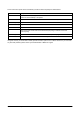
Appendix Call Progress Tone Generation Dial Tone Code Country Ring Back Tone Busy Tone Error Tone1 Error Tone2 Freq. Cadence Freq. Cadence Freq. Cadence Freq. Cadence Freq. Hz second Hz second Hz second Hz second Hz second Australia 425*25 cont. 400*25 0.4on 0.2off 0.4on 2.0off 425 0.375on 0.375off 425 0.375on 0.375off 425 1on 1off 02 Argentina 425 cont. 425 1.0on 4.0 off 425 0.3on 0.2off 425 0.3on 0.4off 425 1on 1off 03 Belgium 425 cont. 425 1.0on 3.
Dial Tone Code Country Ring Back Tone Busy Tone Error Tone1 Error Tone2 Freq. Cadence Freq. Cadence Freq. Cadence Freq. Cadence Freq. Hz second Hz second Hz second Hz second Hz Cadence second 32 UK 350+440 cont. 400+450 0.4on 0.2off 0.4on 2.0off 400 0.375on 0.375off 400 0.4on 0.35off 0.225on 0.525off 400 1on 1off 33 USA/Canada 350+440 cont. 440+480 2.0on 4.0off 480+620 0.5on 0.5off 480+620 0.25on 0.25off 480+620 1on 1off Note1: Cont.
CADENCE (In Seconds) Frequency (Hz) T1ON T1OFF T2ON T2OFF Australia 25 0.4 0.2 0.4 2.0 02 Belgium 25 1.0 3.0 03 Brazil 25 1.0 4.0 04 China 25 1.0 3.0 05 Egypt 25 2.0 4.0 06 France 25 1.5 3.5 07 Germany 25 3.5 5.5 0.79 1.1 08 Greece 25 1.0 4.0 09 India 25 0.4 0.2 0.4 2.0 10 Israel 25 2.0 3.0 11 Italy 25 1.0 4.0 12 Japan 25 1.0 2.0 13 Korea 25 1.0 3.0 14 Malaysia 25 2.0 3.0 15 New Zealand 25 2.0 3.0 16 Poland 25 2.0 3.
Ans. Q.5 Ans. Q.6 Ans. Q.7 Ans. Q.8 Ans. Q.9 Ans. Q.10 Ans. Q.11 Ans. Q.12 Ans. of ATA211G. Can I still surf the internet when ATA211G is power down? No. You can not surf Internet if ATA211G is power down. You must power ON the ATA211G to enable Internet surfing on your PC. Else, connect the PC directly to the internet. I am using the ATA211G to make VoIP calls and surf internet. I have connected my PC to LAN port of ATA211G. Can I still make VoIP calls when my PC is shut down or not connected? Yes.
There are two important passwords for the configuration of ATA211G viz Admin Password and User Password. Admin password protects the access to whole configuration while User password protects the access to only few configuration of ATA211G. If you forgot the user password but you still have access to admin password, you can login to Web Jeeves and change the user password.
Q.27 Ans. ATA211G does not get registered to GSM network? Check whether the SIM card is properly inserted and it is activated. Check SIM PIN. Check the availability of good GSM signal. Check the connectivity of antenna etc. (Refer SIM PIN feature in Mobile Port topic and 'Signal Strength' for more details) Q.28 Incoming calls on Mobile port are not being placed on FXS Port however, caller still gets ring back tone. Check the connectivity of analog phone to the FXS port of ATA211G. Ans. Q.29 Ans.
Acronyms ASCII American Standard Code for Information Interchange CLI Caller Line Identification CPT Call Progress Tone CPTG Call Progress Tone Generation CWT Call Waiting Tone DHCP Dynamic Host Configuration Protocol DND Do Not Disturb DNS Domain Name Service DST Daylight Savings Time DTMF Dual Tone Multi-Frequency FEC Forward Error Correction FTP File Transfer Protocol GMT Greenwich Mean Time GSM Global Systems for Mobile Communications IANA Internet Assigned Numbers Authority
RBT Ring Back Tone RFC Request for Comments RTP Real Time Transport Protocol SIP Session Initiation Protocol SLT Single Line Telephone SNTP Simple Network Time Protocol SOHO Small Office Home Office STUN Simple Traversal of UDP over NAT TCP Transmission Control Protocol TFTP Trivial File Transfer Protocol UDP User Datagram Protocol URI Uniform Resource Identifier URL Universal Reference/Resource Locator VAD Voice Activity Detection WAN Wide Area Network VoIP Voice Over Interne
Features at a Glance Description Feature Code To enter programming code for Admin #19-Admin Password To enter programming code for User #18-User Password To exit programming mode 0 Speed Dialing #9-Index Number To default Login Password #*** Make a new call #81 Disconnect the call #82 Selective Trunk Access- Mobile #83 Selective Trunk Access-SIP1 #84 Selective Trunk Access-SIP2 #85 Selective Trunk Access-SIP3 #86 Matrix SETU ATA211G System Manual 159
System Commands Command Meaning Allowed to? 11-WAN IP Address-#* To program the WAN IP Address Admin and User 12-LAN IP Address-#* To program the LAN IP Address Admin and User 13-Subnet Mask-#* To program the Subnet Mask of WAN port Admin and User 14-Subnet Mask-#* To program the Subnet Mask of LAN port Admin and User 15-Code-#* To program the connection type of WAN port; where, Code = 1 for DHCP, Code = 2 for PPPoE and Code=3 for Static Admin and User 16-Code-#* To enable/disable 'L2 VLA
Command Meaning Allowed to? 72-Code-#* Set/Cancel Call Waiting; where, Code=1 to set and Code=2 to cancel Call Waiting Admin and User 81-#* To know the Signal Strength on phone LCD Admin and User 82-Code-#* To enable/disable CLIR on Mobile Port Only Admin 99-#* Cancel all features Admin and User Matrix SETU ATA211G System Manual 161
Product Specifications PORT NAME APPLICATION NO.
• • • • • • Full Duplex Audio Echo Cancellation: G. 168, with programmable tail length of 8 - 32 msecs. Forward Error Correction (FEC) Voice Activity Detection (VAD) Fax using T.38 and Pass Through Flash Timer Programming Voice Codec's G.711 (a-Law and -Law), G.729, G.
Dimension (W x H x D) 104mm x 27mm x 80mm (4.09" x 1.06" x 3.15") Power Supply External Adaptor: 12VDC@ 1.25Amp.
Warranty Statement Matrix warrants to its consumer purchaser any of its products to be free of defects in material, workmanship and performance for a period of 15 months from date of manufacturing or 12 months from the date of installation which ever is earlier. During this warranty period, Matrix will at its option, repair or replace the product at no additional charge if the product is found to have manufacturing defect.
Except for the obligations specifically set forth in this Warranty Policy Statement, in no event shall Matrix be liable for any direct, indirect, special, incidental or consequential damages whether based on contract or any other legal theory and where advised of the possibility of such damages. Neither Matrix nor any of its distributors, dealers or sub-dealers makes any other warranty of any kind, whether expressed or implied, with respect to Matrix products.
Regulatory Information Matrix SETU ATA211G System Manual 167
168 Matrix SETU ATA211G System Manual
Open Source Licensing Terms and Conditions • The firmware of this product also includes some of the Open-Source software released under GNU General Public License (GPL) Version 2. Terms of this license is printed in full below. GNU GENERAL PUBLIC LICENSE Version 2, June 1991 Copyright (C) 1989, 1991 Free Software Foundation, Inc., 51 Franklin Street, Fifth Floor, Boston, MA 02110-1301 USA Everyone is permitted to copy and distribute verbatim copies of this license document, but changing it is not allowed.
We protect your rights with two steps: (1) copyright the software, and (2) offer you this license which gives you legal permission to copy, distribute and/or modify the software. Also, for each author's protection and ours, we want to make certain that everyone understands that there is no warranty for this free software.
of it, thus forming a work based on the Program, and copy and distribute such modifications or work under the terms of Section 1 above, provided that you also meet all of these conditions: a) You must cause the modified files to carry prominent notices stating that you changed the files and the date of any change.
cost of physically performing source distribution, a complete machine-readable copy of the corresponding source code, to be distributed under the terms of Sections 1 and 2 above on a medium customarily used for software interchange; or, c) Accompany it with the information you received as to the offer to distribute corresponding source code.
7. If, as a consequence of a court judgment or allegation of patent infringement or for any other reason (not limited to patent issues), conditions are imposed on you (whether by court order, agreement or otherwise) that contradict the conditions of this License, they do not excuse you from the conditions of this License.
10. If you wish to incorporate parts of the Program into other free programs whose distribution conditions are different, write to the author to ask for permission. For software which is copyrighted by the Free Software Foundation, write to the Free Software Foundation; we sometimes make exceptions for this. Our decision will be guided by the two goals of preserving the free status of all derivatives of our free software and of promoting the sharing and reuse of software generally. NO WARRANTY 11.
MERCHANTABILITY or FITNESS FOR A PARTICULAR PURPOSE. GNU General Public License for more details. See the You should have received a copy of the GNU General Public License along with this program; if not, write to the Free Software Foundation, Inc., 51 Franklin Street, Fifth Floor, Boston, MA 02110-1301 USA. Also add information on how to contact you by electronic and paper mail.
176 Matrix SETU ATA211G System Manual
Index A AC Impedance 54 Admin 16 Answer Signaling 53 Automatic Number Translation 44 DNS Address 61 Static DNS 61 E Echo Cancellation 54 End of Dialing 136 C G Call Hold 105 Call Release Timer 65 Call Toggle 109 Call Transfer 107 Call Transfer - Attended 107 Call Transfer - Blind 107 Call Transfer-Attended 107 Call Transfer-Blind 107 Class of Service 52, 61 Cloned 62 Connection Type DHCP 60 PPPoE 60 Static 60 Current Date 148 Current Time 148 General Request Timer 68 D Daylight Saving Time 85 Debug
SIP Over TCP 67 SIP Provisional Timer 68 SIP Trunk Mode 26 Speed Dialing 123 Static Routing 88 Syslogs 95 T TCP NAT Keep Alive Interval 67 Three-party Conference 113 Time Offset 85 Transmit Gain 46 U UDP NAT Keep Alive Interval 67 Unique 62 User 16 V VLAN header 61 VLAN ID 61 VLAN/CoS Layer RTP CoS 62 SIP CoS 61 Vocoders 33 Voice Activity Detection (VAD) 65 Volume 55
Magyarországon a Matrix Telecom Ltd. képviselete, Matrix termékek importőre, kizárólagos forgalmazója: 1095 Budapest, Mester u. 34. Telefon: *218-5542, 215-9771, 215-7550, 216-7017, 216-7018 Fax: 218-5542 Mobil: 30 940-1970, 20 949-2688 E-mail: delton@delton.hu Web: www.delton.hu Version 2, February 2011 www.matrixtelecom.