
Technical data


Configuration software for SINAUT ST7
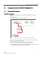
1.8 Configuring connections in the SINAUT Configuration Tool
Software
System Manual, 07/2009, C79000-G8976-C222-07
83
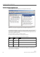
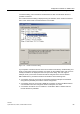
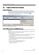
The labeling of the individual connection point in the basic setting describes the relevant
subscriber with:
Subscriber number / Station name / Module / Interface.
Example:
5 / Station 3 / CPU 312 / MPI (2)
The representation can be set to meet individual requirements using the
Extras / Options
menu.
Functions of connection configuration
To make configuration of the required connections as simple as possible for the user, the
SINAUT Configuration Tool uses the following strategy:
● The entire currently configured network is analyzed. All potential communication
subscribers from the SINAUT perspective are assigned a subscriber number if they do
not already have one. The subscriber numbers for CPU modules and third-party stations
are assigned starting at no. 1, for TIM modules there are assigned starting at no. 1001.
● A tracking algorithm detects ALL connections in the current network. These connections
can also extend over several LANs and SINAUT networks. The connections permitted
based on specified rules are represented on the right as
possible connections
in a tree
structure.
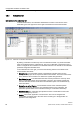
● SINAUT connections that have already been configured are displayed in the left-hand
window for
configured connections
. Each of the connections loaded there is then checked
to establish whether its configured parameters match the current network and hardware
configuration. If this is not the case, and error message indicating incorrect connections is
displayed as soon as the connection configuration is opened and the bad connection is
displayed in red in the
configured connections
window.
If a station of the type
other station
or
SIMATIC S5
was configured in NetPro, connections
from the stations to stations of the type ST7, PG/PC, or an ST7cc control center are not
displayed. This does not, however, mean that these connections do not exist. These
connections are in fact displayed in the opposite direction; this means, for example, from an
ST7 station to a station of the type
other station
or
SIMATIC S5
.
As a general rule, a connection displayed in the
configured connections
in only one direction,
works in both directions.
Selecting the required CPU-CPU connections
If no connections are displayed in the left-hand window, the required connections must be
transferred from the right-hand window. Follow the steps outlined below:
1. Expand the tree structure by clicking on the branch symbol (+) or by double-clicking on
the connection group. The tree structure opens.
2. Select a
possible connection
in the right-hand window.
3. Enter the possible connection as a
configured connection
in the left-hand window by
– selecting the
Edit / Apply
menu or
– pressing the right mouse button and selecting
Apply
in the displayed context menu.
If alternative communication paths exist and you want to use them, expand the possible
connection structure in the
possible connections
by double-clicking on it and select the
connection and apply it.