
Technical data


Configuration software for SINAUT ST7
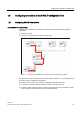
1.8 Configuring connections in the SINAUT Configuration Tool
Software
82 System Manual, 07/2009, C79000-G8976-C222-07
View of the
Connection Configuration
window
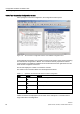
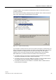
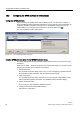
After opening the connection configuration, the configuration window opens.
Figure 1-42 The
Connection Configuration
window of the SINAUT Configuration Tool
In the right-half of the window, the
possible connections
are listed in a tree structure resulting
from the network configuration in NetPro. The connections actually required and used for
communication in the SINAUT installation must be transferred from the right-hand to the left-
hand window
Configured connections
.
The two lists display the number of connections involved.
The entries in the connection tables must be interpreted as follows:
Table 1- 2 Symbols in the connection list of the connection configuration
Level Symbol Meaning
1
Connection starting point
2
Connection end point
3
Alternative path
4
Connection node over which the connection runs
Invalid connections are displayed in red as shown in the example of a connection that no
longer exists due to reconfiguration.