
Technical data


Configuration software for SINAUT ST7
1.6 Configuring networks and network nodes in STEP 7 / NetPro
Software
68 System Manual, 07/2009, C79000-G8976-C222-07
Note
If the interface is set to "RS-485", you will need to set the internal terminating resistor of
the module for the RS-485 bus.
If the TIM 4R-IE is at the start of the RS-485 bus, which is normally the case, select the
setting "yes". Otherwise select "no".
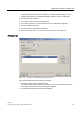
●
Operating mode
:
This setting specifies whether the interface connected to the current node will be
operated in interrupt or in DMA mode. Only one of the two interfaces of a TIM module
may be operated in DMA mode.
Range of values: Interrupt (block), DMA, Interrupt (single characters)
Default: Interrupt (block)
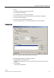
– Operating mode = Interrupt (block)
This operating mode applies to the transmit and receive direction.
The default mode Interrupt (block) is suitable for all connections. Four characters are
transferred per block. Following this, there is an interrupt. The received characters are
checked only after a complete message has arrived.
– Operating mode = DMA
This operation mode applies to the transmit and receive direction.
The DMA mode should be used for connections with a high baud rate or heavy
message traffic, however not for GSM networks.
Only one of the two interfaces of a TIM module may be operated in DMA mode.
– Operating mode = Interrupt (single characters)
This operating mode is used only in the receive direction. In the transmit direction, the
block mode continues to the used.
This interrupt mode is suitable for extremely bad lines. An interrupt is triggered per
transmitted character and each character this analyzes immediately after it is received
allowing extremely good diagnostics of transmission errors. This mode is more reliable
than the block mode but is slower.
●
Extra transm. time
:
This is an offset added to the transmit retry time. The send retry time is calculated
automatically on the TIM.
From the
Extra transm. time
parameter, the character delay time can also be calculated
(character delay time = extra transm. time divided by 5).
An offset time should be entered in the
Extra transm. time
input box, for example when
the send retry time cannot be calculated completely as is the case with satellite
transmissions or wireless links over repeaters.
Range of values: 0 .. 65535 ms
Default: 0 (for M1 or M20 module: 400 ms)
●
Number of spontaneous messages
:
This function is available only for the station and node station node types.
Range of values: 0 .. 255
Default for dedicated lines: 20
Default for dial-up networks: 200
– Number = 0 in polling mode:
All spontaneous messages pending at the time of the first polling message are
transferred.