
Technical data


Configuration software for SINAUT ST7
1.6 Configuring networks and network nodes in STEP 7 / NetPro
Software
46 System Manual, 07/2009, C79000-G8976-C222-07
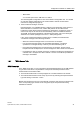
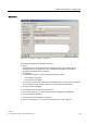
Starting the parameter assignment dialogs for networks and network nodes
If you double-click on a network or network node icon or select the
Object Properties
menu
in the context menu (right-hand mouse button), the
Properties
dialog opens to allow you to
set parameters. Here, you can connect modules with networking capability with the networks
and adapt the properties of the relevant object to your requirements. All parameters have
default settings that simplify parameter assignment.
First the network attachments are made.
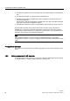
1.6.1 Generating network attachments
To network a project, the communication-compliant modules (for example CPU or TIM) must
be connected to suitable networks. The modules in the station icons in the project window of
the network configuration include interface and network node icons displayed in different
colors according to the network type.
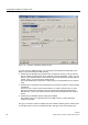
Figure 1-17 Icon of a master TIM station in the project window of the network configuration
containing a TIM module and three network nodes
The station icon shows a master to containing a communication-compliant TIM 44D module.
This module has three network nodes, visible as small squares in the module icon. If these
network nodes are not connected to a network as in the example, the relevant network node
is not networked.
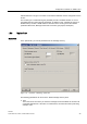
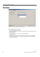
You connect network nodes with the networks using the mouse by dragging the network
node icons to the line of the required network.
Figure 1-18 Station with three network nodes, two of which are networked