
Technical data


SINAUT Diagnostics and Service tool
3.3 SINAUT diagnostics
Software
System Manual, 07/2009, C79000-G8976-C222-07
365
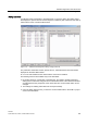
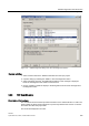
Figure 3-21
TIM Extended Diagnostics
dialog
Operator activities
1. Select a subscriber in the
SINAUT subscriber list
of the open project.
2. First open the
Module Information / Diagnostic Buffer tab
by selecting the
STEP 7
Diagnostics/ Module Information / Diagnostic Buffer tab
and click on the
Settings
button.
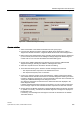
3. Make sure that the
Update display during operating mode transition
option is deselected
(no check mark) at the bottom of the
Settings for Display Diagnostic Buffer
dialog and
confirm with
OK
. You can leave the
Module Information
dialog open.
4. Change to the SINAUT Diagnostics and Service tool and open the
TIM Extended
Diagnostics
dialog by selecting the
SINAUT / TIM Diagnostics
menu.
5. Select the
required function
in the field on the left of the dialog.
6. Then select the following in the
Firmware module and diagnostics level
area
– The required firmware component in the
Module
list box and
– The required level (area) in the
Level
list box.
7. Confirm your entries by clicking on the
Activate
button. A dialog
Loading
opens briefly
and indicates that the activation information for extended diagnostics is being sent to the
module by displaying a progress bar. Once the information has been sent successful, the
Loading
and
TIM Extended Diagnostics
dialogs are closed.
Any diagnostic messages are activated on the selected module and displayed in the
active diagnostic buffer.
If multiple extended diagnostic messages are activated, you must confirm the activation
of the message output for each individual firmware component and level with
Activate
.
8. Change back to the
Module Information / Diagnostic Buffer tab
that is still open and click
on
Update
, if necessary, several times. Extended diagnostic messages are displayed in
hexadecimal code.
If necessary, save the diagnostic messages as a text file as described for the
Module
Information
function.