
Technical data


Configuration software for SINAUT ST7
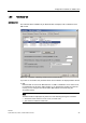
1.5 Setting TIM module parameters
Software
System Manual, 07/2009, C79000-G8976-C222-07
35
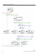
● ST7cc
No settings need to be made in an Ethernet network in which ST7cc (or ST7sc) is always
time master.
● Station 10, TIM 3V-IE
This TIM is connected directly to ST7cc, the time master, over Ethernet. You will
therefore need to enable the Ethernet port of the TIM as slave for time synchronization.
An interval of 1 minute is recommended.
For the CPU in station 10, you may want to enable synchronization on the S7-300
backplane bus. Refer to the notes above in the section "Station 2, TIM 3V-IE".
Note
If the station is connected to an Ethernet network for which fees are charged, for example
via GPRS, it may be more economic to set an interval longer than 1 minute.
● Master TIM 4R-IE
This TIM has two networked Ethernet accesses. Make the following settings.
– On Ethernet(1):
There is an ST7cc computer (= time master) on this Ethernet network. Enabling the
interface as time slave. An interval of 1 minute is recommended.
– On Ethernet(3):
Enable the interface of the TIM as time master on this Ethernet network. Here, you
can set an interval different from the interval for the slave interface on Ethernet(1).
Apart from synchronizing the stations connected to Ethernet(3), the TIM also supplies the
stations in the dedicated line or dial-up network by synchronizing the TIMs in these
stations that, in turn, supply their CPUs. In these networks, you do not need to make
settings for the TIMs. These TIMs obtain their parameters from the time parameter
settings made centrally for the particular SINAUT network (dedicated line or dial-up
network) refer to the section: Setting parameters for SINAUT networks, Time Services
tab).
● Station 11, TIM 3V-IE / station 12, TIM 3V-IE Advanced
The TIMs in both stations are attached to Ethernet(3) in which the "master TIM 4R-IE" is
enabled as time master. This means that you will need to enable both TIMs as time
slaves. The interval should be identical to that on the time master on Ethernet(3).
For the CPU in station 11 or 12, you may want to enable synchronization on the S7-300
backplane bus. Refer to the notes above in the section "Station 2, TIM 3V-IE".
● Station 13, two TIM 3V-IE Advanced modules
This station functions as a node station. Each of the two TIMs has a network access to
Ethernet that you enable as time slave for the TIM on Ethernet(3) and as time master on
the other TIM on Ethernet(4).
To allow the TIM connected to Ethernet(4) to adopt the role of time master, it must be
synchronized by the TIM connected to Ethernet(3). The TIMs are synchronized over the
S7-300 backplane bus. To allow this, you will need to enable time synchronization over
the S7-300 backplane bus on both TIMs.
The hierarchical structure of the time synchronization network is continued here. If
necessary, you can set an interval for the master interface (right-hand TIM) that differs
from the interval for the slave interface (left-hand TIM).