
Technical data


Configuration software for SINAUT ST7
1.5 Setting TIM module parameters
Software
System Manual, 07/2009, C79000-G8976-C222-07
31
The following rule applies if there are several TIMs in the S7-300 rack or several TIMs on the
MPI bus:
1. Time synchronization must be enabled for all TIMs and set to the same time interval.
After startup, only one of the TIMs will actually behave as the time master. This is
negotiated automatically by the TIMs. The TIM acting as time master synchronizes all the
local SINAUT nodes known to it. The other TIMs act as slaves and allow themselves to
be synchronized by the current master. If the TIM acting as master fails, one of the other
TIMs automatically takes over the time master function until the failed master TIM is
available again.
While the "time master" or "time slave" roles are negotiated automatically on the S7-300
backplane bus or MPI, with the Ethernet interfaces of the TIM, the role of master or slave
must be specified explicitly. The following rules apply:
1. If the Ethernet port of the TIM is connected to an Ethernet on which there is also an
ST7cc or ST7sc PC, the PC in this network is always time master, in other words, the
relevant Ethernet port of the TIM must be set to the "slave" function.
2. In an Ethernet network without ST7cc or ST7sc PC, the Ethernet port of one of the TIMs
must be set to master and all others to slave. If the master function is set for more than
one TIM on the Ethernet network, an error message is generated during the verification
performed in the SINAUT node management.
3. Each Ethernet port to be synchronized by a master must be enabled as a slave.
Otherwise synchronization is not accepted on this port. The setting of the synchronization
interval or time of a slave should be identical to that of the master on the Ethernet
network because the slave monitors whether or not the synchronization takes place at the
specified intervals or at the specified time. Setting a shorter interval or a different time
would lead to error messages in the diagnostic buffer of the TIM.
Note
The error message is not exactly coordinated with the interval or the point in time.
• With an interval, the error message comes after 2.5 times the set interval. Example: At
an interval of 2 hours, the error message is entered only after 5 hours.
• If a specific time is selected, a tolerance of 2.5 hours is allowed before the error is
signaled.
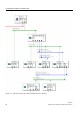
In the following example, meant to illustrate the two sections of a SINAUT project, shows
where and which time synchronization setting must be made.