
Technical data


Configuration software for SINAUT ST7
1.10 TD7onTIM software package
Software
System Manual, 07/2009, C79000-G8976-C222-07
137
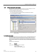
Address
[Byte]:
Input field for the byte number in the selected memory area
Explanation: The
operator input status byte
is the output by of the
OpInputMonitor
system object.
In the
operator input status byte
, the next 3 bits are assigned (explanation
see above).
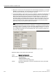
Byte assignment of the
operator input status byte
Bit: .7 .6 .5 .4 .3 .2 .1 .0
Status: 8 7 6 5 4 1-out-of-
n error
Input
error
Input OK
For
value:
0 0 0 0 0 1 1 1
Unused bits are set to 0
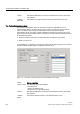
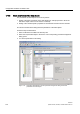
Parameter settings in the
Hardware input
area:
Name: Max. Input Time
Range of
values:
Enter value x 1 [s] (10 corresponds to 10 seconds)
Default: 0
Explanation: Monitoring time for commands entered over hardware inputs, or setpoints
and parameters whose transmission is triggered over a hardware input. If
the 1 signal is set at these hardware inputs for longer than defined in
Max.
Input Time
, then the
input error
bit is set in the
operator input status byte
.
Further hardware entries are not processed as long as the
input error
bit is
set.
The
Max. Input Time
is specified in seconds.
A time of at least 30 seconds is recommended (entry: 30).
0 (zero) can be entered if the parameter is not required.
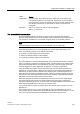
Name: Min. Input Time
Range of
values:
Enter value x 0.1 [s] (10 corresponds to 1 second)
Default: 0
Explanation: Delay time for commands entered over hardware inputs, or setpoints and
parameters whose transmission is triggered over a hardware input. The
message is entered in the send buffer of the TIM only if the currently
entered command, setpoint for parameter remains unchanged for the
specified delay time and no other command or setpoint input is detected
during this time.
The
Min. Input Time
is specified in tenths of seconds.
A time of at least 1 second is recommended (entry: 10).
0 (zero) can be entered if the parameter is not required.