MAXTRIX-X88 8 x 8 HDMI Matrix Operation Manual
DISCLAIMERS The information in this manual has been carefully checked and is believed to be accurate. SPATZ assumes no responsibility for any infringements of patents or other rights of third parties which may result from its use. SPATZ assumes no responsibility for any inaccuracies that may be contained in this document. SPATZ also makes no commitment to update or to keep current the information contained in this document.
SAFETY PRECAUTIONS Please read all instructions before attempting to unpack, install or operate this equipment and before connecting the power supply. Please keep the following in mind as you unpack and install this equipment: • Always follow basic safety precautions to reduce the risk of fire, electrical shock and injury to persons. • To prevent fire or shock hazard, do not expose the unit to rain, moisture or install this product near water. • Never spill liquid of any kind on or into this product.
CONTENTS 1. Introduction.............................................. 1 2. Applications ............................................. 1 3. Package Contents .................................. 1 4. System Requirements.............................. 1 5. Features .................................................... 1 6. Operation Controls and Functions......... 2 6.1 Front Panel ..........................................2 6.2 Rear Panel...........................................3 6.3 Side Panel ...............
1. INTRODUCTION The 8 x 8 HDMI Matrix is a fabulous device for organizing and distributing your HDMI signals. With 8 HDMI input ports and 8 HDMI output ports this device allows a great amount of sources and display to be used motivationally. Moreover, with plenty of control systems such as IR, RS-232 and remote control allow user for all kinds of control habit and occasion to be used. Further, the EDID control settings unlocked the information display freely present. 2.
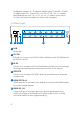
. OPERATION CONTROLS AND FUNCTIONS 6.1 Front Panel 1 2 3 4 5 6 1 LCD This monitor displays your setting information with each input and output selection. 2 POWER button & LED Press this button to turn on the device and the green LED will illuminate when the power is on. When the LED illuminate in red it is in standby mode 3 LOCK button & LED Press this button to lock all the buttons on the panel. To unlock, just press it again.
example, output A ~ D wish to select input 1 and E ~ H wish to select input 2. Press Out →A→B→C→D→In→1→Menu, and then press Out →E→F→G→H→In→2→Menu. If the menu button is not press the selection will not be changed. 6.2 Rear Panel 1 2 3 4 5 6 7 1 LAN Reserved. 2 RS-232 This slot is to connect with D-Sub 9pin cable from the PC/NB device for RS-232 control. 3 IR-IN This slot is to connect with the IR extender included in the package for IR signal receiving from the remote control of this device.
7 DC24V This slot is to plug the power cord with adaptor included in the package and then connect them with AC wall outlet for power supply. 6.3 Side Panel 1 1 VENTILATOR This is the fan ventilation area, DO NOT block this area or cover it with any object. 6.4 Remote Control 1 Power Press this button to switch on the device or set it to standby mode. 2 IN 1 1 A 2 B 3 C 4 D 5 E Input ports selection 1~8. 3 OUT Output ports selection A~H.
6.
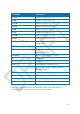
Command Description A1~A8 Switch Output A to 1~8 B1~B8 Switch Output B to 1~8 C1~C8 Switch Output C to 1~8 D1~D8 Switch Output D to 1~8 E1~E8 Switch Output E to 1~8 F1~F8 Switch Output F to 1~8 G1~G8 Switch Output G to 1~8 H1~H8 Switch Output H to 1~8 ABCE…1~ABCD…8 Switch Output ABCD… to 1~8 at the same time SETIP Setting IP. SubNet.
6.7 Telnet Control Before attempting to use the telnet control, please ensure that both the Matrix (via the 'LAN /CONTROL' port) and the PC/Laptop are connected to active networks. Note: Please do not connect both the Matrix and the PC/Laptop with a single CAT5e/6 cable as it will not access the telnet function. To access the telnet control in Windows 7, click on the 'Start' menu and type "cmd" in the Search field then press enter.
Once in the command line interface (CLI) type "telnet", a space, then the IP address of the unit you wish to control, a space and "23", then hit enter. Note: The IP address of the Matrix can be displayed on the device's LCM monitor by pressing the Menu button twice. This will bring us into the device which we wish to control. Type "HELP" to list the available commands. Type “IPCONFIG” To show all IP configurations.
9
8. SPECIFICATIONS Video Bandwidth 255 MHZ/6.75 GBPS Input Ports 8×HDMI, 1×RS-232, 1×IR Receiver, 1×Mini USB Type B (For firmware update only), 1×RJ-45 Output Ports 8×HDMI HDMI Input Cable Distance 15m/8-bit, 10m/12-bit HDMI Output Cable Distance 15m/8-bit ,15m/12-bit ESD Protection Human-body Model: ± 8kV (Air-gap discharge) ± 4kV (Contact discharge) Power Supply 24 V/6.