
Owner's manual


LCD0821 rev 2
10
The RS-232 connector on the PC cable is wired so that a standard “straight through” serial cable may be
used to connect the module to a standard serial port such as COM ports on PCs. Note that this device
complies with the EIA232 standard in that it uses signal levels from ± 3V to ± 12V. It will not operate
correctly at TTL (0 to +5V) levels.
Pin Number
on LCD
Pin Number
on Host
Direction
Description
1 N/A - +5Vdc
2 3 to LCD module Data In
3 5 - Ground
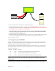
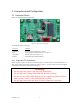
2.1.3 Applying Power via the RS-232 Connector
The power connector on the PC cable is wired as shown in Figure 2-7. Power may be provided to the
module by pin 1 of the 3pin strip header connector instead of through the 4-pin SIP. If power is to be
applied using the 3 pin strip header.
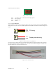
2.1.4 TTL Communications
The LCD0821 does not communicate with TTL by default, the following modification must be made:
Solder the jumper in the picture below:
Figure 2-8 TTL modification
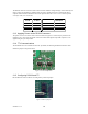
2.1.5 Configuring RS-232 and I
2
C
RS-232 baud rate and I
2
C address are configured by means of jumpers.
Figure 2-9 RS-232 jumpers