
User`s guide


User Datagram Protocol (UDP)
3-21
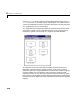
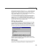
As seen in the figure above, the data types of each of the signals have to be
specified as a cell array of strings in the correct order. Once this is done, the
block will automatically convert itself to one with the correct number of input
ports. There is always one output port. The supported data types are:
double,
single, int8, uint8, int16, uint16, int32, uint32, and boolean. The byte
alignment field specifies how the data types are aligned. The possible values
are: 1, 2, 4 and 8. The byte alignment scheme is simple, and ensures that each
element in the list of signals starts on a boundary specified by the alignment
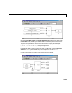
relative to the start of the vector. For example, say the Input port data types
are specified as
{’uint8’,’uint32’,’single’,’int16’,’double’}
and an alignment of 4 is used. Assume also that all the signals are scalars. The
first signal will then start at byte 0 (this is always true), the second at byte 4,
the third at byte 8, the fourth at byte 12, and the fifth at byte 16. Note that the
sizes of the data types used in this example are 1, 4, 4, 2, and 8 bytes
respectively. This implies that there are “holes” of 3 bytes between the first and
second signal and 2 bytes between the fourth and fifth signal.
A byte alignment of 1 means the tightest possible packing. That is, there are
no holes for any combination of signals and data types.