
User`s guide


I/O Driver Blocks
2-11
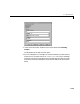
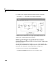
3 In the Simulink window, double-click the output block labeled Analog
Output.
The dialog box for the D/A converter opens.
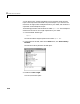
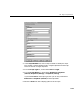
4 Fill in the dialog box. For example, for one channel enter [1] in the Channel
Vector box, for an ouptut level of
±10 V enter the code [-10] in the Range
Vector box. Enter the same sample time you entered for the step size in the
Simulation Parameters dialog box. Enter the base address for this ISA-bus
board.