
User`s guide


2 Advanced Procedures
2-10
Your next task is to define the I/O block parameters. See “Defining I/O Block
Parameters”.
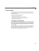
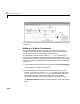
Defining I/O Block Parameters
The I/O block parameters define values for your physical I/O boards. For
example, I/O block parameters include channel numbers for multichannel
boards, input and output voltage ranges, and sample time.
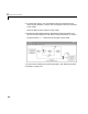
This procedure uses the Simulink model
xpcosc.mdl as an example, and
assumes you have added an analog input and an analog output block to your
model. To add an I/O block, see either “Adding I/O Blocks with the xPC Target
Library” on page 2-4 or“Adding I/O Blocks with the Simulink Library Browser”
on page 2-7.
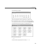
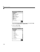
1 In the Simulink window, double-click the input block labeled Analog Input.
The dialog box for the A/D converter opens.
2 Fill in the dialog box. For example, for a single channel enter 1 in the
Number of Channels box, choose
±10 V for the input range, and choose
single-ended (16 channels)for the MUX-switch position. Enter the
same sample time you entered for the step size in the Simulation
Parameters dialog box. Enter the base address for this ISA-bus board.
The Block Parameters dialog box should look similar to the figure shown
below.