
User`s guide


2 Advanced Procedures
2-6
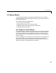
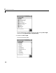
5 From the block library, click-and-drag the name of an A/D board to the
Simulink block diagram. Likewise, click-and-drag the name of a D/A board
to your model.
Simulink adds the new I/O blocks to your model.
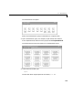
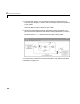
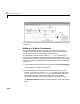
6 Remove the signal generator block and add the analog input block in its
place. Remove the scope block and add the analog output block in its place.
The demo model
xpcosc should look like the figure shown below.
Your next task is to define the I/O block parameters. See “Defining I/O Block
Parameters” on page 2-10.