
Specifications


3 GPIB I/O Support
3-12
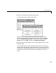
GPIB_Send_Receive(2).Command = ’rd 16’;
GPIB_Send_Receive(2).RecData = ’%f’;
GPIB_Send_Receive(2).RdLength = 20;
GPIB_Send_Receive(2).OutputPorts = [1];
GPIB_Send_Receive(2).OutputDataTypes = {’double’};
GPIB_Send_Receive(2).Timeout = 0.15;
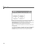
This example did not need a termination structure. But if it did, the format
of the structure is the same as the initialization structure. For example, a
termination structure could have a message with the
.Command and
.SendData fields.
GPIB_Termination(1).Command
GPIB_Termination(1).SendData
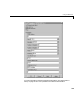
3 From the File menu, click Save As. In the Save As File dialog box, enter the
name of the M-file script. For example, enter
GPIB_Messages.m
4 Close the text editing window.
5 In the MATLAB command window, type the name of the M-file script you
created with the GPIB structures. For example, type
GPIB_Messages
MATLAB loads and runs the M-file script to create the message structures
in the MATLAB workspace needed by the GPIB driver blocks.
6 Open your Simulink model, or press Ctrl+D.
The GPIB driver blocks are updated with the information from the
structures. For example, inputs and outputs defined in the structures are
now visible on the driver blocks.
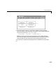
7 Connect the input and output ports on the RS-232 driver blocks to other
blocks in your Simulink model.
Your model should look similar to the figure shown below.