
Specifications


Using GPIB Drivers
3-11
Your next task is to create the MATLAB message structures that the GPIB
driver blocks use to sequence commands to the GPIB controller. See “Creating
GPIB Message Structures” on page 3-11.
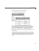
Creating GPIB Message Structures
GPIB drivers use MATLAB structures to send and receive messages, and map
the input and output ports on the GPIB driver blocks to the data written and
read from the GPIB devices.
After you add GPIB driver blocks to your Simulink model, you can create the
message structures to communicate with the GPIB controller. You need to
create and load these structures into the MATLAB workspace before you build
your target application. The easiest way to create these structures is to create
an M-file and load that M-file into the MATLAB workspace.
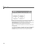
1 In the MATLAB command window, and from the File menu, point to New,
and then click
M-file.
A MATLAB text editor window opens.
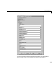
2 Enter the initialization and send/receive messages. Each message is an
element in a MATLAB structure array with a series of fields. For
information and examples of these fields, see “GPIB Initialization and
Termination Message Structures” on page 3-17 and “GPIB Send/Receive
Message Structure” on page 3-18.
As an example, if you have a multimeter attached to a GPIB bus that has an
address of 16, needs the initialization command
:conf:volt:dc to set the
device to read DC voltages, and uses the command
:read? to read one
voltage value, you could type the following.
Note Field names in the structures are case-sensitive.
GPIB_Initialize(1).Command = ’wrt 16’;
GPIB_Initialize(1).SendData = ’:conf:volt:dc’;
GPIB_Send_Receive(1).Address= 16;
GPIB_Send_Receive(1).Command = ’wrt 16’;
GPIB_Send_Receive(1).SendData = ’:read?’;
GPIB_Send_Receive(1).Timeout = 0.05;