
Specifications


VSBC-6
17-29
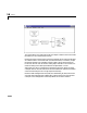
VSBC-6 Digital Output
Scaling Input to Output
Driver Block Parameters
Channel Vector - Enter a numbers between 1 and 16 to select the number of
digital output lines used. This driver allows the selection of individual digital
output lines in any order.
For example, to use the first, second and fifth digital output lines, enter
[1,2,5]
Number the lines beginning with 1, even if the board manufacturer starts
numbering the lines with 0.
Sample Time - Enter the base sample time or a multiple of the base sample
time.
VSBC-6 Watch Dog
Block Parameters
Show Enable Port - Select this check box to show, on the driver block, the
digital input that allows enabling and disabling.
Show Reset Port - Select this check box to show , on the driver block, the
digital input that resets the computer if set to 1.
Sampletime - Enter the base sample time or a multiple of the base sample
time.
Hardware Output Block Input Data Type Scaling
TTL double < 0.5 = TTL low
>
0.5 = TTL high