
Specifications


17 Versalogic
17-28
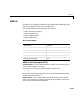
The following table is a list of the ranges for this driver and the corresponding
range codes.
For example, if the first channel is -10 to + 10 volts and the second and fifth
channels are 0 to +5 volts, enter
[-10,5,5]
Sampletime - Model base sample time or a multiple of the base sample time.
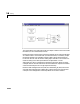
VSBC-6 Digital Input
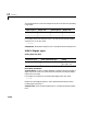
Scaling Input to Output
Driver Block Parameters
Channel Vector - Enter a numbers between 1 and 16 to select the number of
digital input lines used. This driver allows the selection of individual digital
input lines in any order.
For example, to use the first, second and fifth digital input lines, enter
[1,2,5]
Number the lines beginning with 1, even if the board manufacturer starts
numbering the lines with 0.
Sample Time - Enter the base sample time or a multiple of the base sample
time.
Input range (V) Range code Input range (V) Range code
-10 to +10 -10 0 to +10 10
-5 to +5 -5 0 to +5 5
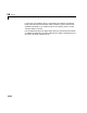
Hardware Input Block Output Data Type Scaling
TTL double TTL low = 0.0
TTL high = 1.0