
Specifications


DM7420
25
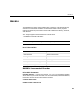
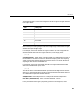
The following table is a list of the ranges for this driver given the gain entered
in the gain vector.
Notice that by increasing the gain code the voltage range is decreased. The gain
divides the input voltage range.
For example, if the first channel has a gain code of 1 (10 volt range) and the
second and fifth channels have a gain code of 2 (5 volt range), enter
[1,2,2]
Coupling Vector - Enter either 0 (single-ended) or 1 (differential) for each of
the channels in the channel vector to choose the coupling code. The coupling
vector must be the same length as the channel vector. This driver allows the
coupling of each channel to be different.
For example, if the first and second channels are single-ended and the fifth
channel is a differential input, enter
[0,0,1]
The driver selects a second differential input 8 channels higher than the first
channel. In the example above, the driver would select the thirteenth channel
as a differential input with the fifth channel.
Sample Time - Base sample time or a multiple of the base sample time.
PCI Slot (-1:autosearch) - Enter a number between -1 and n.
If only one board of this type is physically present in the target PC, enter
Gain Range (V)
10 to 10
20 to +5
4 0 to 2.5
8 0 to 1.25
16 0 to 0.625
32 0 to 0.312