
Specifications


15 Real Time Devices
20
BaseAddress - Enter the base address of the board. This entry must
corresponds to the DIP-switch settings on the board. For example, if the base
address is 300 (hexadecimal), enter
0x300
DM6804 FM Capture
This block programs the AMD9513A for capturing FM signals.
There is one output for relative frequency compared to the base frequency. To
get the actual frequency, multiply the base frequency by the relative frequency.
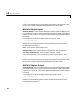
Scaling Input to Output
Driver Block Parameters
Counter - From the list, choose 1, 2, 3, 4 or 5. This selects which counter the
driver block uses to determine the FM. In each case, one block is needed for
each counter.
Frequency Base - From the list, choose F1=5MHz, F2=500kHz, F3=50kHz,
F4=5kHz, or F5=500Hz to set the base frequency.
Sample Time - Enter the base sample time or a multiple of the base sample
time. The sample time indicates the update rate of registration on the input
(Duty Cycle)
BaseAddress - Enter the base address of the board. This entry must
corresponds to the DIP-switch settings on the board. For example, if the base
address is 300 (hexadecimal), enter
0x300
Hardware Output Block Input Data Type Scaling
TTL double 0 to 1