
Specifications


DM6804
17
Scaling Input to Output
Driver Block Parameters
Counter - From the list, choose 1, 2, 3, 4, or 5 to select which counter is used
with this driver block. In each case, one block is needed for each counter.
Frequency Base - From the list, choose F1=5MHz, F2=500kHz, F3=50kHz,
F4=5kHz, or F5=500Hz to set the base frequency.
Initial Relative Output Frequency - Enter a value between 0 and 1. The
Initial Relative Output Frequency defines the initial output frequency of the
FM-signal relative to the Frequency Base during driver initialization.
For example, if the initial output frequency of a square wave has to be 17.5
kHz, then choose F2=500kHz as the Frequency Base and enter
0.175 as the
Initial Relative Output Frequency. 500kHz x 0.175 = 87.5 kHz
Duty Cycle - Enter a value between 0 and 1 to set the duty cycle. The Duty
Cycle is held fixed during simulation.
Initial Toggle State - From the list, choose high or low. The Initial Toggle
State sets the initial digital level (high or low) of the output. For example, if
the Duty Cycle is 0.25 and the Initial Toggle State is High, the first 25% of the
period will have a high level and the last 75% will have a low level.
Sample Time - Enter the base sample time or a multiple of the base sample
time. The sample time indicates the update rate of registration on the input
(Duty Cycle)
BaseAddress - Enter the base address of the board. This entry must
corresponds to the DIP-switch settings on the board. For example, if the base
address is 300 (hexadecimal), enter
0x300
DM6804 Counter FM & ARM
The DM6804 has one AM9513A chip with 5 counters.
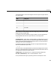
Hardware Output Block Input Data Type Scaling
TTL double 0 to 1