
Specifications


DM6420
5
Note While this board has programmable input ranges of +5, +10 and 0 to
10, this driver sets the input range to +10, and then lets you select different
input ranges by choosing different gains.
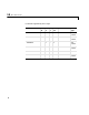
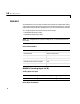
The following table is a list of the ranges for this driver given the gain entered
in the gain vector.
Notice that by increasing the gain code the voltage range is decreased. The gain
divides the input voltage range.
For example, if the first channel has a gain code of 1 (10 volt range) and the
second and fifth channels have a gain code of 2 (5 volt range), enter
[1,2,2]
Sample Time - Base sample time of a multiple of the base sample time.
BaseAddress - Enter the base address of the board. It is important that this
entry corresponds to the DIP-switch settings on the board. For example, if the
base address is 300 (hexadecimal), enter
0x300
Gain Range (V)
1-10 to 10
2-5 to +5
4 -2.5 to 2.5
8 -1.25 to 1.25