
Specifications


15 Real Time Devices
4
DM6420 Analog Input
Scaling Input to Output
Driver Block Parameters
Channel Vector - Enter numbers between 1 and 16. This driver allows the
selection of individual A/D channels in any order. The number of elements
defines the number of A/D channels used.
For example, to use the first, second and fifth channels, enter
[1,2,5]
Number the channels beginning with 1 even if the board manufacturer starts
numbering the channels with 0.
Coupling Vector - Enter either 0 (single-ended) or 1 (differential) for each of
the channels in the channel vector to choose the coupling code. The coupling
vector must be the same length as the channel vector. This driver allows the
coupling of each channel to be different.
For example, if the first and second channels are single-ended and the fifth
channel is a differential input, enter
[0,0,1]
The driver selects a second differential input 8 channels higher than the first
channel. In the example above, the driver would select the thirteenth channel
as a differential input with the fifth channel.
Gain Vector - Enter
1, 2, 4, or 8 for each of the channels in the channel vector
to choose the gain code of that channel. The gain vector must be the same
length as the channel vector. This driver allows the gain of each channel to be
different.
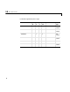
Hardware Input Block Output Data Type Scaling
volts double 1