
Specifications


14 National Instruments
14-100
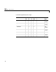
Scaling of Input to Output
Driver Block Parameters
Channel Vector - Enter numbers between 1 and 8 to select the digital output
lines used with this port. This driver allows the selection of individual digital
output lines in any order. The number of elements defines the number of digital
lines used.
For example, to use all of the digital outputs for one port, enter
[1,2,3,4,5,6,7,8]
Number the lines beginning with 1 even if the board manufacture starts
numbering the lines with 0.
Port - From the list choose either A, B, or C. The I/O board has a 8255 chip
with 3 ports. The Port parameter defines which port of the 8255 chip is used
for this driver block. Each port has a maximum or 8 digital lines that can be
configured as inputs or outputs depending on which driver block is chosen. In
each case, one block is needed for each port.
Chip - From the list choose 1, 2, 3, or 4.
Sampletime - Enter a base sample time or a multiple of the base sample time.
Sampletime - Enter a base sample time or a multiple of the base sample time.
PCI Slot (-1:autosearch) - Enter a number between -1 and n.
If only one board of this type is physically present in the target PC, enter
-1
Hardware Output Block Input Data Type Scaling
TTL double < 0.5 = TTL low
>
0.5 = TTL high