
Specifications


DAS-1800HR
13-5
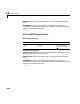
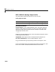
The following table is a list of the ranges for this driver given the gain entered
and the range chosen.
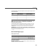
MUX - From the list, choose either 8 differential, 16 single-ended, or 16
single-ended common mode. Your choice must correspond to the
MUX-switch setting on the board.
Common-mode is similar to single-ended mode but the negative wire of the
source to be measured is connected to input AI-SENSE instead of LLGND.
Sample Time - Base sample time of a multiple of the base sample time.
BaseAddress - Enter the base address of the board. It is important that this
entry corresponds to the DIP-switch settings on the board. For example, if the
base address is 300 (hexadecimal), enter
0x300
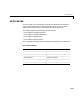
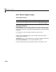
DAS-1800HR Digital Input
Scaling Input to Output
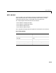
Driver Block Parameters
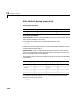
Number of Channels - Enter a number between 1 and 8 to select the number
of digital input lines used with this port.
Gain Bipolar Range (V) Unipolar Range (V)
1 -10 to +10 0 to 10
2 -5 to + 5 0 to +5
4 -2.5 to 2.5 0 to 2.5
8 -1.25 to +1.25 0 to 1.25
Hardware Input Block Output Data Type Scaling
TTL double TTL low = 0.0
TTL high = 1.0