
Specifications


13 Keithley Metrabyte
13-4
DAS-1800HR Analog Input (A/D)
Scaling Input to Output
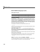
Driver Block Parameters
Channel Vector - If 16 single-ended or 16 single-ended common mode is
chosen from the MUX list, then enter numbers between 1 and 16 to select the
individual channels. If
8 differential is chosen from the MUX list, then enter
numbers between 1 and 8 to select the A/D channels used. This driver allows
the selection of individual A/D channels in any order. The number of elements
defines the number of A/D channels used/
For example, to use the first, second and fifth channels, enter
[1,2,5]
Number the channels beginning with 1 even if the board manufacturer starts
numbering the channels with 0.
Gain Vector (1,2,4,8) - Enter
1, 2, 4, or 8 for each of the channels in the
channel vector to choose the gain code of that channel. The gain vector must be
the same length as the channel vector. This driver allows the gain of each
channel to be different.
Notice that by increasing the gain code the voltage range is decreased. The gain
divides the input voltage range.
For example, if the first channel has a gain code of 1 (10 volt range) and the
second and fifth channels have a gain code of 2 (5 volt range), enter
[1,2,2]
Range - From the list, choose either Bipolar or Unipolar.
The range setting defines if the board is working in bipolar or unipolar input
mode. This setting is the same for all of the selected channels.
Hardware Input Block Output Data Type Scaling
volts double 1