
Specifications


2 RS232 I/O Support
2-18
Alternatively, you could access the xPC Target block library from the
Simulink Library Browser. In the Simulink window, and from the
View
menu, click
Show Library Browser. In the left pane, double-click xPC
Target
, and then click RS-232.
5 Drag-and-drop the RS-232 Send and RS-232 Receive blocks into your
Simulink model.
6 Add a Signal Generator, Gain, and xPC Target Scope block.
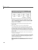
Your model should look similar to the figure below. Notice, you cannot
connect to the inputs on the RS-232 Send block and the outputs on the
RS-232 Receive block, because they are not defined or visible. The inputs
and outputs are defined in a MATLAB massage structure, and visible only
after you load that structure into the MATLAB workspace and update your
Simulink model.
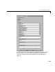
7 Double-click the first RS-232 Setup block. Enter values to configure the
COM1 port on the target PC.
For example, if the COM1 and COM2 ports of the target are connected with
a RS-232 null modem cable and setting serial communication to 5760 baud,
8 databits, and 1 stopbit. You Block Parameter dialog box should look
similar to the figure shown below.
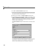
Note If you are not using an initialization or termination structure, in the
Initialization Struct and Termination Struct boxes, enter two single
quotes.