
Specifications


AD 512
12-7
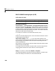
AD 512 Digital Output
Scaling Input to Output
Channel Vector - Enter a numbers between 1 and 8. This driver allows the
selection of individual digital line numbers in any order. The number of
elements defines the number of digital output lines used.
For example, to use the first, second and fifth digital output lines, enter
[1,2,5]
Number the lines beginning with 1, even if the board manufacturer starts
numbering the lines with 0.
Sample Time - Enter the base sample time or a multiple of the base sample
time.
BaseAddress - Enter the base address of the board. This entry must
correspond to the DIP-switch settings on the board. For example, if the base
address is 300 (hexadecimal), enter
0x300
Hardware Output Block Input Data Type Scaling
TTL double < 0.5 = TTL low
>
0.5 = TTL high