
Specifications


12 Humusoft
12-4
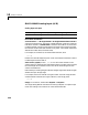
AD 512 Analog Input (A/D)
Scaling Input to Output
Driver block Parameter
Channel Vector - Enter numbers between 1 and 8. This driver allows the
selection of individual channels in any order. The number of elements defines
the number of A/D channels used.
For example, to use the first, second and fifth channels, enter
[1,2,5]
Number the channels beginning with 1 even if the board manufacturer starts
numbering the channels with 0.
Range Vector - Enter a range code for each of the channels entered in the
channel vector. The range vector must be the same length as the channel
vector. This driver allows a different range for each channel.
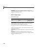
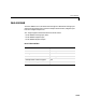
The following table is a list of the ranges for this driver and the corresponding
range codes.
For example, if the first channel is -10 to + 10 volts and the second and fifth
channels are 0 to +1 volts, enter
[-10,1,1]
Sample Time - Model base sample time or a multiple of the base sample time.
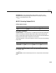
Hardware Input Block Output Data Type Scaling
volts double 1
Input range (V) Range code Input range (V) Range code
-10 to +10 -10 0 - 10 10
-5 to +5 -5 0 - 5 5