
Specifications


RS-232 Synchronous Mode
2-13
Your next task is to create the MATLAB message structures that the RS-232
driver blocks use to sequence commands to the RS-232 device. See “Creating
RS-232 Message Structures (Synchronous)” on page 2-13.
Creating RS-232 Message Structures (Synchronous)
RS-232 drivers use MATLAB structures to send and receive messages and map
the input and output ports on the RS-232 driver blocks to the data written and
read from the RS-232 devices.
After you add an RS-232 Setup and RS-232 Send/Receive block to your
Simulink model, you can create the message structures to communicate with
the RS-232 devices. You need to create and load these structures into the
MATLAB workspace before you build your target application. The easiest way
to create these structures is using an M-file and load that M-file into the
MATLAB workspace.
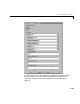
1 In the MATLAB command window, and from the File menu, point to New,
and then click
M-file.
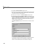
A MATLAB text editor window opens.
2 Enter the initialization, send/receive, and termination messages. Each
message is an element in a MATLAB structure array with a series of fields.
For information and examples of these fields, see “RS-232 MATLAB
Structure Reference” on page 2-31.
For example, you could have an external RS-232 device with an D/A module
that wants a string in the format
’identifier, channel, value;\n’.
Identifier is any string. Channel is an integer value between 1 and 2,
defining which D/A channel to update.
Value is a floating-point value
indicating the new voltage for the D/A output.
Additionally, when the external device receives a legal string, it accepts the
string as an input message, and returns the message
’noerror;\n’. This
message is provided as a confirmation. As an example, you could type the
following