
Specifications


9 ComputerBoards
9-58
[-10,5]
The range settings have to correspond to the DIP-switch settings on the board.
The jumpers by the range DIP-switches on the board all have to be in the XFER
position. The Wait-State jumper has to be in the off position.
Sampletime - Base sample time of a multiple of the base sample time.
BaseAddress - Enter the base address of the board. It is important that this
entry corresponds to the DIP-switch settings on the board. For example, if the
base address is 300 (hexadecimal), enter
0x300
CIO-DDA06 (/12) Digital Input
The CIO-DDA06 has a 8255 chip with 3 ports (A,B,C). Each port has a
maximum of 8 digital I/O lines that can be configured as inputs or outputs.
Use a separate diver block for each port. By selecting the digital input driver
block, the port is configured as input.
Scaling Input to Output
Driver Block Parameters
Channel Vector - Enter numbers between 1 and 8 to select the digital input
lines used with this port. This driver allows the selection of individual digital
input lines in any order. The number of elements defines the number of digital
lines used.
For example, to use all of the digital inputs for one port, enter
[1,2,3,4,5,6,7,8]
Number the lines beginning with 1 even if the board manufacturer starts
numbering the lines with 0.
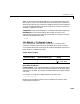
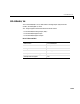
Hardware Input Block Output Data Type Scaling
TTL double TTL low = 0.0
TTL high = 1.0