
Specifications


CIO-DDA06 (/12)
9-57
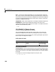
CIO-DDA06 (/12) Analog Output (D/A)
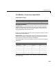
Scaling Input to Output
Driver Block Parameters
Channel Vector - Enter Numbers between 1 and 6. This driver allows the
selection of individual D/A channels in any order. The number of elements
defines the number of D/A channels used. For example, to use the first and
second analog output (D/A) channels, enter
[1,2]
Number the channels beginning with 1 even if the board manufacturer starts
numbering the channels with 0.
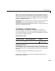
Range Vector - Enter a range code for each of the channels in the channel
vector. The range vector must be the same length as the channel vector. This
board allows the range of each channel to be different.
The following table is a list of the ranges for this driver and the corresponding
range codes.
For example, if the first channel is -10 to +10 volts, and the second channel is
0 to 5 volts, enter
Hardware Output Block Input Data Type Scaling
volts double 1
Input range (V) Range code Input range (V) Range code
-10 to +10 -10 0 to 10 10
-5 to +5 -5 0 to +5 5
-2.5 to +2.5 -2.5 0 to +2.5 2.5
-1.67 to +1.67 -1.67 0 to +1.67 1.67
-.625 to +.625 -0.625