
Specifications


1-5
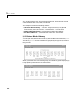
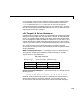
In this example, the third line indicates the location of the ComputerBoards
PCI-DIO48 board. This is known since the ComputerBoards Vendor ID is
0x1307 and the Device ID is 0xb. In this case, you now can see that the
ComputerBoards board is plugged into the PCI slot 11 (Device No.), and that
this value must be entered in the dialog box entry in your I/O device driver for
each model that uses this I/O device.
xPC Target I/O Driver Structures
Properties for xPC Target I/O drivers are usually defined using the Parameter
dialog box associated with each Simulink block. However, for more advanced
drivers, the available fields defined by text boxes, check boxes,and pull down
lists are inadequate to define the behavior of the driver. In such cases, a more
textual description is needed to indicate what the driver has to do at runtime.
Texual in this context refers to a programming language like syntax and style.
xPC Target currently uses a textual description contained in message
structures for the RS232, GPIB, CAN (initialization) and the general counter
drivers (AMD9513).
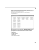
What is a message structure? — A message structure is a MATLAB array
with each cell containing one complete message (command). A message
consists of one or more statements.
Syntax of a message statement — and each statement in a message has the
following format.
Structure_name(index).field_name = <field string or value>
The field names are defined by the driver, and need to be entered with the
correct upper and lower case letters. However, you can choose your own
structure name, and enter that name into the driver Parameter dialog box.
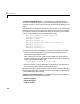
Message structure
First message Second message
Message(1).field
Message(1).field
Message(1).field
Message(1).field
Message(1).field
Message(1).field
Message(1).field
Message(1).field
Message(1).field
Third message