
Specifications


PCI-20023M
8-9
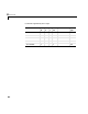
Input Range - Enter an input range code for all A/D channels. This driver does
not allow the selection of a different range for individual channel. The input
range is the same for all A/D channels.
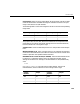
The following table is a list of the ranges for this driver and the corresponding
range codes.
The jumpers W1, W2, W4, W5, W33 on the module must correspond to this
range setting. The switch and jumper settings, that are not mentioned here,
have no influence on running xPC Target.
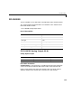
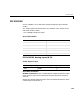
Sample Time - Enter the base sample time or a multiple of the base sample
time.
Module Number (1-3) - Enter a number from 1 to 3 to identify the connector
on the carrier board where the I/O module is inserted. This driver verifies if the
module is placed on the specified module connector.
BaseAddress of Carrier Board (ie. 0xd000) - Enter the base address of the
I/O board. It is important that this entry corresponds to the DIP-switch
settings on the board. For example, if the base address is 300 (hexadecimal),
enter
0x300
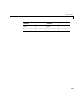
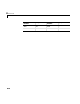
Other jumpers on this board.
The switch and jumper settings, that are not
mentioned here, have no influence on the running of xPC Target.
Input range (V) Range code Input range (V) Range code
-10 to +10 -10 0 - 10 10
-5 to +5 -5
Jumper
Number
Jumper Jumper
Number
Jumper
W6 out W12 out
W8 in W27 out
W9 - W30 -