
Specifications


8 Burr-Brown
8-4
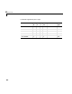
The following table is a list of the ranges for this driver and the corresponding
range codes.
For example, if the first channel is -10 to + 10 volts and the second channel is
0 to +5 volts, enter
[-10,5]
The jumpers W1 to W5, W13, W14, W27, W31, W7 to W11, W30, W32 on the
module must correspond to this range setting.
Sample Time - Enter the base sample time or a multiple of the base sample
time.
Module No - Enter a number from 1 to 3 to identify the connector on the
carrier board where the I/O module is inserted. This driver verifies if the
module is placed on the specified module connector.
BaseAddress or Carrier Board (ie: 0xd000) - Enter the base address of the
board. This entry must correspond to the DIP-switch settings on the board. For
example, if the base address is 300 (hexadecimal), enter
0x300
Input range (V) Range code Input range (V) Range code
-10 to +10 -10 0 - 10 10
0 - 5 5