
Specifications


PCL-818L
7-37
Driver Block Parameters
Channel Vector - If you choose single ended from the MUX list, then enter
channels between 1 and 16. If you choose
differential from the MUX list, then
enter channels between 1 and 8. For example, to use the first and second analog
output (A/D) channels, enter
[1,2]
Number the channels beginning with 1 even if the board manufacture starts
numbering the channels with 0.
Range Vector - Enter a range code for each of the channels in the channel
vector. The range vector must be the same length as the channel vector. This
board allows the range of each channel to be different.
The following table is a list of the ranges for this driver and the corresponding
range codes.
For example, if the first channel is -10 to +10 volts, and the second channel is
-5 to 5 volts, enter
[-10,-5]
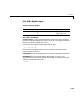
The range settings have to correspond to the DIP-switch settings on the board.
MUX - From the list, choose either single-ended(16 channels) or
differential (8 channels). Your choice must correspond to the MUX-switch
setting on the board.
Sampletime - Base sample time or a multiple of the base sample time.
Input range (V) Range code Input range (V) Range code
-10 to +10 -10
-5 to +5 -5
-2.5 to +2.5 -2.5
-1.25 to +1.25 -1.25
-.625 to +.625 -0.625