
Specifications


PCL-818HD
7-29
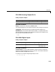
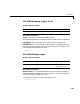
PCL-818HD Analog Output (D/A)
Scaling of Input to Output
Driver Block Parameter
Range - From the list, choose either 0-10V or 0-5V.
The range settings have to correspond to the DIP-switch settings on the board.
Sampletime - Base sample time of a multiple of the base sample time.
BaseAddress - Enter the base address of the board. It is important that this
entry corresponds to the DIP-switch settings on the board. For example, if the
base address is 300 (hexadecimal), enter
0x300
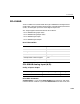
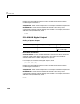
PCL-818HD Digital Input
Scaling of Input to Output
Driver Block Parameters
Channel Vector - Enter numbers between 1 and 16. This driver allows the
selection of individual digital input lines in any order. The number of elements
defines the number of digital lines you use.
For example, to use the first eight digital inputs, enter
[1,2,3,4,5,6,7,8]
Hardware Output Block Input Data Type Scaling
volts double 1
Hardware Input Block Output Data Type Scaling
TTL double TTL low = 0.0
TTL high = 1.0