
Specifications


PCL-726
7-9
Driver Block Parameter
Channel Vector - Enter numbers between 1 and 6. This driver allows the
selection of individual D/A channels in any order. The number of elements
defines the number of D/A channels you use. For example, to use the first and
second analog output (D/A) channels, enter
[1, 2]
Number the channels beginning with 1 even if the board manufacture starts
numbering the channels with 0.
Range Vector - Enter a range code for each of the channels in the channel
vector. The range vector must be the same length as the channel vector. This
board allows the range of each channel to be different.
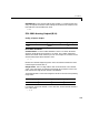
The following table is a list of the ranges for this driver and the corresponding
range codes.
For example, if the first channel is -10 to +10 volts, and the second channel is
0 to 5 volts, enter
[-10,5]
The range settings have to correspond to the DIP-switch settings on the board.
Sampletime - Base sample time of a multiple of the base sample time.
BaseAddress - Enter the base address of the board. It is important that this
entry corresponds to the DIP-switch settings on the board. For example, if the
base address is 300 (hexadecimal), enter
0x300
Input range (V) Range code Input range (V) Range code
0 to +10 10 0 to +5 5