
Specifications


6 ADDI-DATA
6-4
to the APCI-1710-manual for information on how to electrically connect the
encoders to the board.
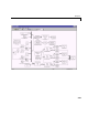
Driver Block Parameters
Function Module. - From the list select 1, 2, 3, or 4. This field specifies which
function module (counter) is used for this block. It has to be programmed with
the incremental encoder firmware. For the same board two blocks cannot have
the same module (channel) specified.
Type of Evaluation - From the list select the type of counter evaluation as
either Virtual Absolute or Reset and Index Output Up-Dating.
Choosing Virtual Absolute allows to get the counter value as an absolute value
after the reference point of the encoder has been reached for the first time. The
first output of the block outputs the actual absolute angle of the connected
encoder in radians. As long as the reference point has not been reached for the
first time, the second block output is zero. If the reference point is reached for
the first time and only for the first time the corresponding counter is reset to
zero and the second output goes to 1. From then on the output 1 outputs an
absolute angle even in the case the encoder is turned multiple times. The
second output can be used for controlling or switching different Simulink
submodels.
Choosing Reset and Index Output Up-Dating allows to get the counter value in
the range of 0..2*pi or –pi..+pi where the counter is reset every time the
reference point is reached. The first output of the block outputs the actual
angle of the connected encoder in radian. As long as the reference point has not
been reached for the first time, the second block output is zero. Every time the
reference point is reached the counter is reset to zero and depending on the
direction of the encoder at this event the output value is either incriminated or
decremented by the value 1. In other words: the second output outputs the
actual number of turns n since the reference point has been reached for the first
time. If the second output is multiplied by 2*pi and added to value of the first
output one get an absolute multi-turn angle, even if the counter is reset
periodically.
Mode - From the list choose single, double, or quadruple. This parameter
specifies the phase detection mode ie. how many phase-changes are detected of
the specified module (see the APC1-1710-manual).